In our digitally-driven world, printed circuit boards (PCBs) are the unsung heroes, forming the backbone of nearly all electronic devices. From the smallest microchip in your phone to the complex control systems of industrial machinery, PCBs rely on a variety of crucial components. This article demystifies these essential building blocks, offering a clear and comprehensive guide suitable for both beginners and experienced engineers, emphasizing not just their presence, but their vital roles in every circuit.
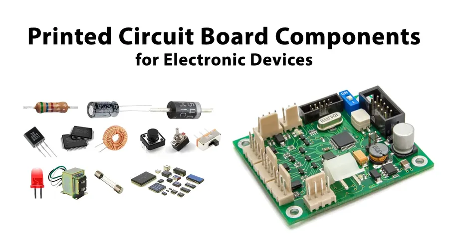
Printed Circuit Boards (PCBs) serve as the foundational platform for electronic devices, providing both mechanical support and electrical connections for various electronic components. Essentially, a PCB is a structured network that allows components to interact, enabling complex circuits to perform specific functions as designed. Without PCBs, the intricate connections required for modern electronics would be impractical to achieve.
At its core, a PCB facilitates two primary functions: the mechanical mounting of components and the electrical routing that allows these components to communicate and operate together. This is achieved through a combination of conductive pathways (traces), insulating materials, and connection points.
The interaction between components on a PCB is determined by the layout and routing of these conductive traces. These traces are precisely designed to ensure proper signal flow, preventing shorts and signal degradation. Different types of components—passive, active, connectors, etc.—are placed strategically to optimize the circuit's performance and functionality. Understanding these components, as detailed in subsequent sections, is essential to comprehending how PCBs function and how electronic devices operate.
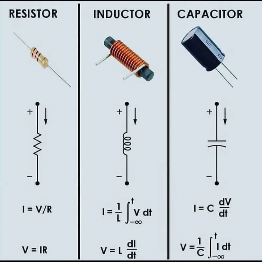
Passive components are fundamental building blocks of any electronic circuit, including PCBs. Unlike active components, they do not require an external power source to operate and cannot amplify or switch electronic signals. Instead, they modify signals through their inherent properties, primarily manipulating voltage, current, and impedance. Resistors, capacitors, and inductors are the core elements within this category, serving distinct but equally crucial roles in circuit functionality.
| Component | Symbol | Function | Key Parameters | Typical Applications |
|---|---|---|---|---|
| Resistor | Zigzag line or Rectangle | Limits current flow, divides voltage | Resistance (Ohms), Tolerance, Power Rating | Current limiting, voltage dividers, biasing circuits |
| Capacitor | Two parallel lines | Stores electrical charge, filters signals | Capacitance (Farads), Voltage Rating, Tolerance | Filtering, decoupling, energy storage |
| Inductor | Coil or series of loops | Stores energy in magnetic field, filters signals | Inductance (Henries), Current Rating, Quality Factor | Filtering, tuning circuits, chokes |
Understanding the role of each passive component is crucial for PCB design and analysis. Resistors regulate the flow of current and establish voltage levels within the circuit. Capacitors store electrical energy and are instrumental in filtering out unwanted signal frequencies. Inductors store energy in a magnetic field and are also used in filtering and energy storage applications. These components do not introduce gain or switching functionality and perform as defined by physical laws.
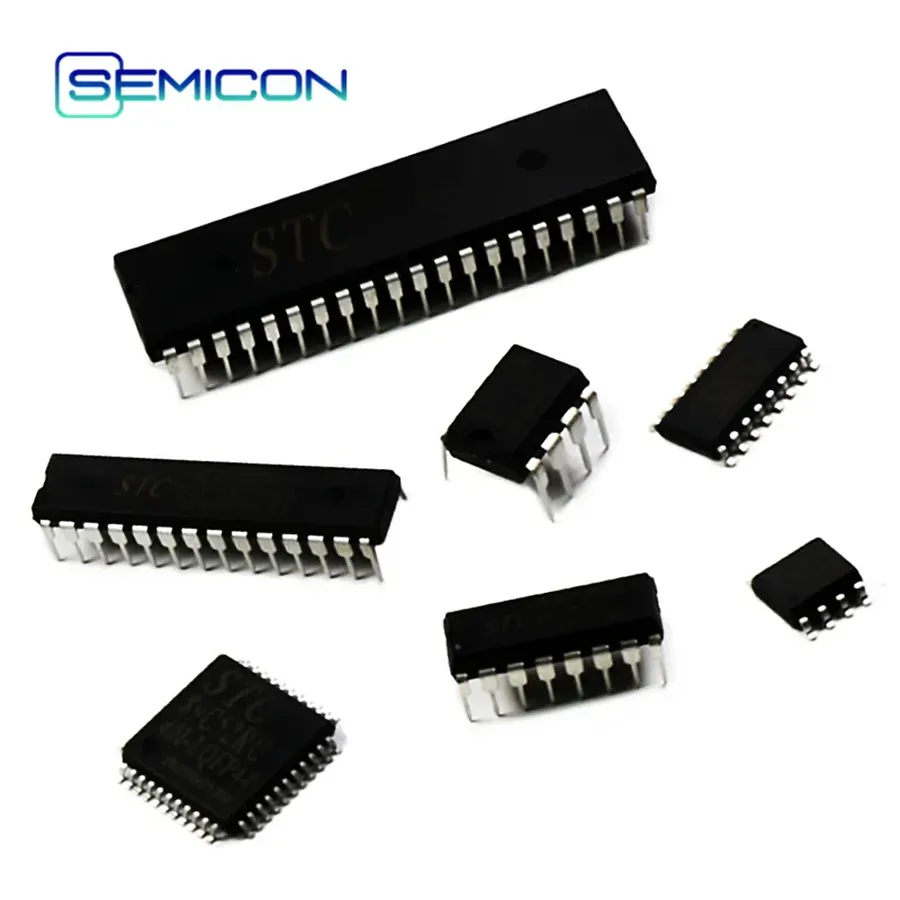
Active components are the dynamic elements within a Printed Circuit Board (PCB), actively influencing current flow and enabling complex functions. Unlike passive components, which simply react to electrical signals, active components can amplify, switch, or otherwise manipulate these signals, forming the basis of all electronic processing and control. This section will explore the roles of key active components such as diodes, transistors, and integrated circuits (ICs).
| Component | Function | Description |
|---|---|---|
| Diodes | Current Direction Control | Allow current to flow primarily in one direction; used for rectification, signal detection, and voltage regulation. Different types of diodes exist, such as rectifiers, LEDs, and Zener diodes, each with specific characteristics. |
| Transistors | Switching and Amplification | Three-terminal semiconductor devices that can act as electronic switches or amplifiers. They are the fundamental building blocks of modern electronics, with types like BJTs and MOSFETs serving a multitude of roles, from signal amplification to logic gates. |
| Integrated Circuits (ICs) | Complex Function Execution | Miniaturized electronic circuits (also called chips) containing a large number of transistors and other components interconnected to perform specific functions, such as microprocessors, memory, amplifiers, and logic functions. They form the core of most complex electronics. |
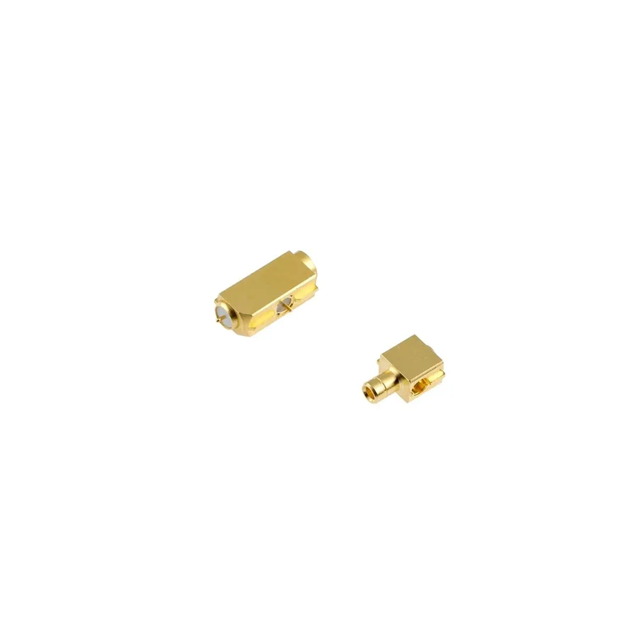
Beyond the fundamental active and passive components, numerous other specialized elements play vital roles in the functionality of a Printed Circuit Board (PCB). These components, while not always the core of the circuit, provide crucial connectivity, sensing capabilities, or specific electrical transformations that allow the PCB to perform its intended application.
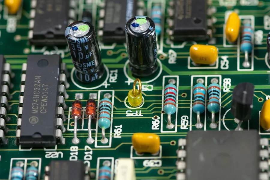
Accurate identification of PCB components is crucial for effective troubleshooting, repair, and design modification. This section details how to decode the markings, symbols, and codes found on various electronic components, thereby enhancing your ability to work with PCBs.
The identification process involves understanding component markings, which often include manufacturer logos, part numbers, date codes, and electrical specifications (e.g., resistance, capacitance, voltage ratings). These markings can be read directly on the component body or from accompanying datasheets. Understanding schematic symbols is equally important; these represent components in circuit diagrams, which provide a functional view of the PCB.
| Component Type | Typical Markings | Schematic Symbol Example | Key Identification Features |
|---|---|---|---|
| Resistor | Color bands (EIA code), resistance value, tolerance | Zigzag line | Color bands indicate resistance; numeric value codes |
| Capacitor | Capacitance value (numeric or alphanumeric), voltage rating, tolerance | Two parallel lines | Numeric values indicate capacitance; polarity indicated on some types |
| Inductor | Inductance value, physical size and shape | Coiled wire | Often marked with inductance value or a numerical code. |
| Diode | Part number, cathode marking | Triangle pointing to a bar | Bar indicates cathode; alphanumeric code specifies type |
| Transistor | Part number, manufacturer logo | Three lines with arrows or symbols | Alphanumeric code indicates type; package indicates function |
| Integrated Circuit (IC) | Part number, manufacturer logo, date code | Rectangle with pins | Part number specifies function; pin configuration is critical |
Proper component identification also requires knowledge of international standards, such as the EIA (Electronic Industries Alliance) color code for resistors and the standard symbols defined by IEEE (Institute of Electrical and Electronics Engineers). Component datasheets, provided by manufacturers, are an invaluable resource for detailed specifications and pin-out information.
Selecting the appropriate PCB components is crucial for ensuring the reliable and efficient operation of any electronic device. This decision process requires a thorough understanding of various electrical, environmental, and mechanical factors. Choosing components that precisely meet the design specifications prevents premature failure, optimizes performance, and minimizes the risk of catastrophic issues.
| Factor | Description | Importance |
|---|---|---|
| Voltage Rating | The maximum voltage a component can safely handle without breakdown. | Critical for preventing component failure due to overvoltage. |
| Current Rating | The maximum current a component can continuously conduct without overheating. | Essential for preventing thermal damage and ensuring long-term reliability. |
| Power Rating | The amount of power (measured in watts) a component can dissipate safely. | Important for managing heat generated during circuit operation and preventing component damage due to excess heat. |
| Tolerance | The permissible variation from the specified nominal value of a component. | Affects circuit accuracy and stability, particularly in precision applications. |
| Thermal Characteristics | The component's ability to handle heat generation and dissipation, including thermal resistance and operating temperature range. | Crucial for reliability, particularly in high-power or high-temperature environments. |
| Operating Frequency | The range of frequencies at which a component can operate effectively. | Vital for signal integrity and performance in high-frequency applications. |
| Physical Size and Package | Dimensions and packaging of the component, which affects PCB layout and assembly. | Influences design density, manufacturability, and component placement options. |
| Environmental Conditions | Operating temperature range, humidity, and other environmental factors the component can tolerate. | Essential for ensuring the reliability of devices used in harsh or variable conditions. |
| Material Compatibility | Ensuring the component materials are compatible with other PCB materials and manufacturing processes. | Prevents corrosion, delamination, and other manufacturing-related problems. |
| Cost | The price of the component and the effect it will have on the overall cost of the product. | Must be balanced with the performance and reliability required for the application. |
| Datasheet Specifications | Detailed characteristics and performance parameters from the component's technical datasheet. | The foundation for accurate design and component selection; must be carefully reviewed before design |
Understanding common failure modes in PCB components is crucial for effective troubleshooting and maintenance. This section delves into the typical causes of component failure and offers practical diagnostic and repair advice, emphasizing the use of a multimeter for accurate assessments.
The following are some key areas to focus on when troubleshooting PCB components:
Below are general steps for troubleshooting using a multimeter:
By understanding these common failure points and employing systematic troubleshooting techniques, you can effectively diagnose and repair issues within your PCB, minimizing downtime and maximizing component lifespan.
This section addresses common inquiries regarding PCB components, their operational roles, and their integration within a circuit board. Understanding these FAQs can help both beginners and experienced professionals in electronics design and troubleshooting.
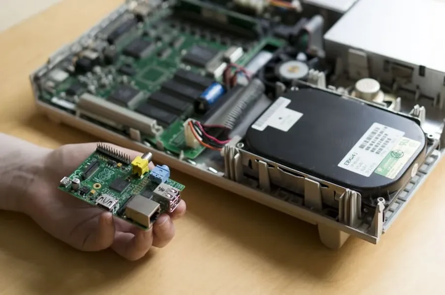
The landscape of PCB components is constantly evolving, driven by the demand for smaller, more efficient, and more powerful electronic devices. Miniaturization, surface mount technology (SMT), and the development of advanced materials are at the forefront of these innovations, promising significant advancements in the capabilities and applications of PCBs.
Understanding PCB components is crucial for anyone working with electronics, from hobbyists to professional engineers. This guide provides a comprehensive overview of essential components, their functions, and how they contribute to the overall performance of PCBs. By mastering these fundamentals and anticipating future developments, you will be well-equipped to handle today's electronic challenges and prepare for tomorrow's innovations. PCB components are the cornerstones of modern electronics, and a thorough understanding of them is essential for both effective design and maintenance.

