Stepping into the world of electronics might seem daunting, but it doesn't have to be. This article introduces the magic of easy electronics, a realm where simple circuits and projects can lead to remarkable discoveries. We'll explore fundamental concepts, guide you through practical starter projects, and reveal how you can get hands-on with this fascinating field. Prepare to unleash your inner maker!
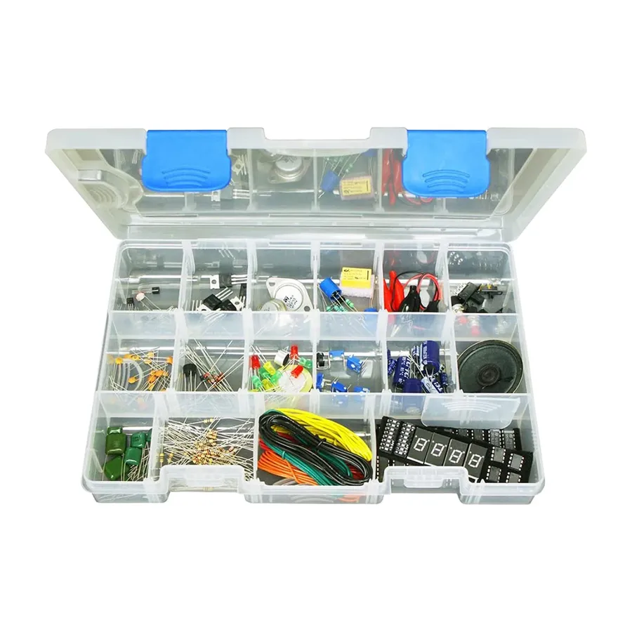
Mastering the identification and function of fundamental electronic components is crucial for anyone starting in electronics. These components, such as resistors, capacitors, LEDs, and transistors, form the building blocks of all electronic circuits, each playing a vital role in controlling and manipulating electrical signals. This section provides a concise overview of these key elements, helping beginners develop a solid foundation.
| Component | Symbol | Function | Identification |
|---|---|---|---|
| Resistor | A zig-zag line | Limits current flow | Color-coded bands indicating resistance value |
| Capacitor | Two parallel lines | Stores electrical charge | Marked with capacitance value and voltage rating |
| LED (Light Emitting Diode) | Triangle with line and two arrows emitting light | Emits light when current flows | Two leads of different lengths, with the longer lead being the anode (+) |
| Transistor | Symbol varies by type (BJT, FET) | Amplifies or switches electronic signals | Three leads, often labeled as base, collector, and emitter (BJT) or gate, source, and drain (FET) |

Embarking on the journey of electronics requires a foundational set of tools. These instruments enable you to construct, test, and troubleshoot basic circuits effectively, providing the necessary hands-on experience to deepen your understanding of electronic principles. This section details the essential tools and their effective use, focusing on safety and best practices.
| Tool | Function | Description | Safety Notes |
|---|---|---|---|
| Multimeter | Measures voltage, current, resistance | Digital multimeters provide accurate readings for testing circuits and components. | Always ensure proper connections before applying power. Select the appropriate range to avoid damaging the meter. |
| Breadboard | Prototyping circuits | A solderless platform to connect components for easy experimentation and testing. | Ensure components are inserted correctly. Avoid excessive force which could damage the breadboard contacts. |
| Soldering Iron (Optional) | Joining electronic components | A heat tool to permanently bond components, needed for robust projects. | Work in a well-ventilated area. Wear protective eyewear and avoid touching the hot tip. Allow adequate cooling before handling soldered parts. |
| Wire Strippers | Remove insulation from wires | Designed to expose the conductive wire core without damaging it for connections. | Select the correct gauge to avoid damaging the wire itself. Do not strip live wires. |
| Needle-nose Pliers | Manipulating components | Useful for holding, bending, and placing small components in a circuit. | Handle components gently to avoid damage. |
| Helping Hand Tool | Holds components while soldering | Features clamps and magnifying glass to aid in soldering and intricate tasks. | Adjust clamps carefully to avoid damaging components |
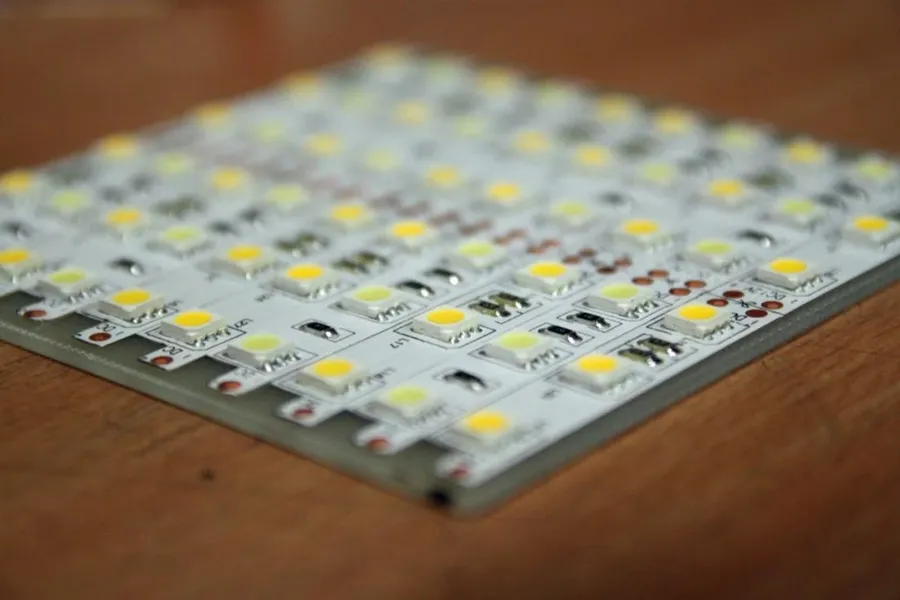
Constructing a basic LED circuit is a fundamental step for anyone venturing into electronics, this project allows beginners to grasp core circuit principles by using a battery, a resistor, and an LED. This hands-on experience will solidify an understanding of current flow and component interaction.
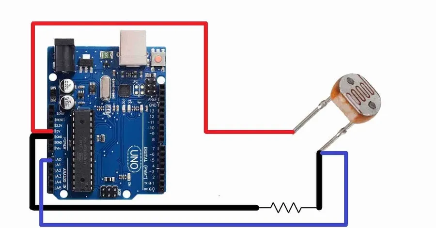
This section details the construction of a fundamental light-sensitive circuit, employing a light-dependent resistor (LDR) to modulate the brightness of an LED. This project demonstrates how a change in light intensity directly influences circuit behavior, providing a hands-on understanding of LDR functionality.
Light-Dependent Resistors (LDRs), also known as photoresistors, are semiconductor devices whose resistance varies inversely with the intensity of incident light. In dark conditions, the resistance of an LDR is high, limiting the flow of current; Conversely, when exposed to light, the resistance decreases, allowing more current to pass. This property makes LDRs ideal for light-sensing applications.
| Component | Function | Value/Type |
|---|---|---|
| LDR | Senses light intensity; resistance decreases with increasing light. | Varies with light intensity, typically 10 kΩ in dark, decreasing to <100Ω in bright light |
| LED | Emits light when current passes through it. | Any standard LED |
| Resistor | Limits the current flowing through the LED to prevent damage. | 220-330 ohms |
| Battery | Provides power to the circuit. | 9V |
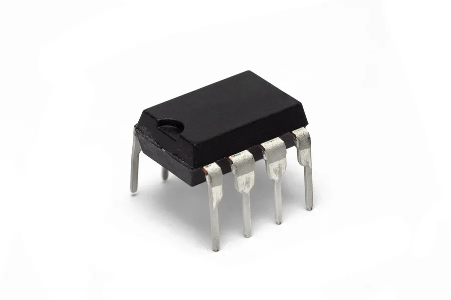
The 555 timer integrated circuit (IC) is a highly versatile and widely used component in electronics, renowned for its ability to generate accurate time delays or oscillations. Its ease of use and adaptability make it a staple in both beginner and advanced electronic projects.
The 555 timer IC primarily operates in three modes: astable, monostable, and bistable. Each mode offers distinct functionalities, making the 555 a cornerstone in various electronic applications. Let's delve into the details of these modes:
Project: A Basic LED Flasher. Using the 555 timer in astable mode, we can build a simple LED flasher. This project will demonstrate a practical application of the 555 timer and how to control the flashing frequency using external components.
| Component | Description |
|---|---|
| 555 Timer IC | The core component for generating oscillations. |
| Resistors | Used to set the timing and frequency of oscillation. |
| Capacitor | Used with resistors to determine timing. |
| LED | The visual indicator of the flashing. |
| Power Supply | To power the circuit. |
| Breadboard | To assemble the circuit without soldering (optional). |
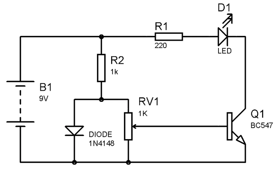
Temperature monitoring circuits provide a tangible demonstration of how electronic components respond to environmental changes. By utilizing thermistors, which are resistors whose resistance varies with temperature, and combining them with LEDs, we can visualize temperature fluctuations. This hands-on approach fosters a deeper understanding of circuit behavior and component interactions.
The core principle involves a voltage divider circuit, where the thermistor’s changing resistance alters the voltage applied to the LED. This variation in voltage affects the LED's brightness, allowing for simple visual monitoring of temperature changes. Understanding this fundamental relationship is critical in designing more complex temperature sensing systems.
| Component | Function | Temperature Response |
|---|---|---|
| Thermistor (NTC) | Temperature Sensor | Resistance Decreases as Temperature Increases |
| Thermistor (PTC) | Temperature Sensor | Resistance Increases as Temperature Increases |
| LED | Visual Indicator | Brightness Varies with Voltage |
| Fixed Resistor | Limits Current, Creates Voltage Divider | Stable Resistance |
This section details a straightforward project that utilizes transistors to create a touch-sensitive circuit, capable of triggering an LED or a buzzer. The core concept involves leveraging the transistor's switching behavior to detect a touch input.
At the heart of this circuit is the transistor, which acts as an electronic switch. A small current at the transistor's base terminal controls a larger current flowing between the collector and emitter terminals. When a human finger bridges two touch points connected to the transistor's base, a small current flows, activating the transistor and completing the output circuit, thus powering the LED or buzzer.
This simple yet effective circuit showcases the fundamental principle of electronic switching.
| Component | Purpose |
|---|---|
| Transistor | Acts as an electronic switch, controlling the current to the output device (LED or buzzer). |
| Resistors | Limit the current flowing into the transistor base and the output device, protecting them from damage. |
| LED/Buzzer | Visual or audible feedback to indicate the touch has been detected. |
| Touch Points | Area touched by the user to close the transistor's input gate. |
This project allows for hands on exploration of how transistors can be used in a variety of different circuit types, enabling a clear understanding of the switching behavior of transistors in a simple context.
This section addresses common queries that beginners often have when venturing into the world of easy electronics projects. We aim to provide clear, concise answers to help you get started and build a solid foundation in electronics.
To further your exploration into easy electronics, a variety of resources are available. These encompass online platforms, educational books, and curated project kits. These resources are designed to facilitate learning, provide hands-on experience, and inspire new project ideas, catering to diverse learning preferences and ensuring a continuous learning journey in electronics.
Easy electronics is not just about assembling circuits; it’s a gateway to understanding the technology that powers our world. From simple LED flashers to touch sensors, every project is a step forward on your journey. Embrace the learning process, experiment without fear, and the world of electronics will become increasingly clear and exciting. What you will learn today is not only knowledge, but also the spirit of exploration and creation. Let's continue to explore together and unlock more possibilities in the field of easy electronics!

