From the intricate electronics in our smartphones to the complex systems in aerospace, printed circuit boards (PCBs) form the backbone of modern technology. Among the various materials used, FR4 stands out as the workhorse of PCB fabrication. This article delves deep into the world of FR4 PCB, exploring its composition, properties, advantages, and limitations. We'll bridge the gap between fundamental understanding and practical application, illuminating why FR4 remains the most popular choice for a wide range of electronic devices.
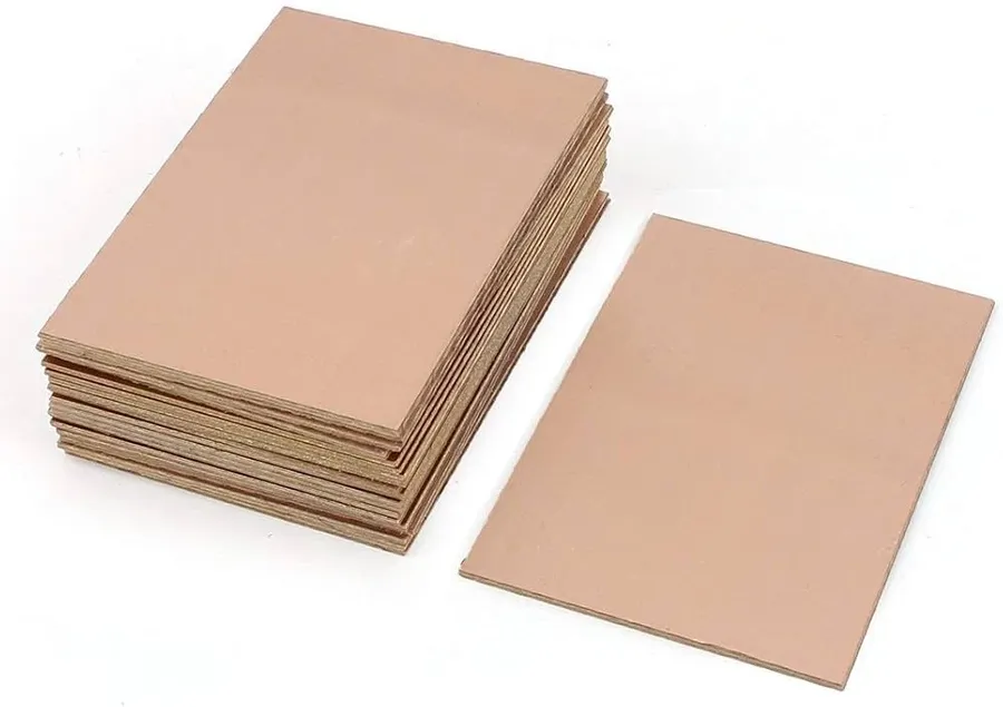
FR4, a ubiquitous term in PCB manufacturing, is not a material itself but rather a National Electrical Manufacturers Association (NEMA) grade designation for a composite material. This composite primarily consists of woven fiberglass cloth impregnated with an epoxy resin binder. It serves as the foundational substrate for the vast majority of printed circuit boards due to its balance of cost, performance, and manufacturability. The specific composition of FR4, the type of glass weave, the epoxy chemistry and the manufacturing process determine the material's final properties.
The term 'flame retardant' is a crucial aspect of FR4's classification. The 'FR' in FR4 stands for flame retardant, indicating that the resin used in the composite has been formulated to self-extinguish when exposed to a flame. This is achieved through the inclusion of specific chemical additives in the epoxy resin which hinder the propagation of fire. This is a critical safety aspect for electronic components, as this flame retardancy reduces the risk of fire in electronic devices that may develop an electrical short or similar problem. The standards for flame retardancy in FR4 are outlined by Underwriters Laboratories (UL) standard 94V-0, a key specification for electronic materials.
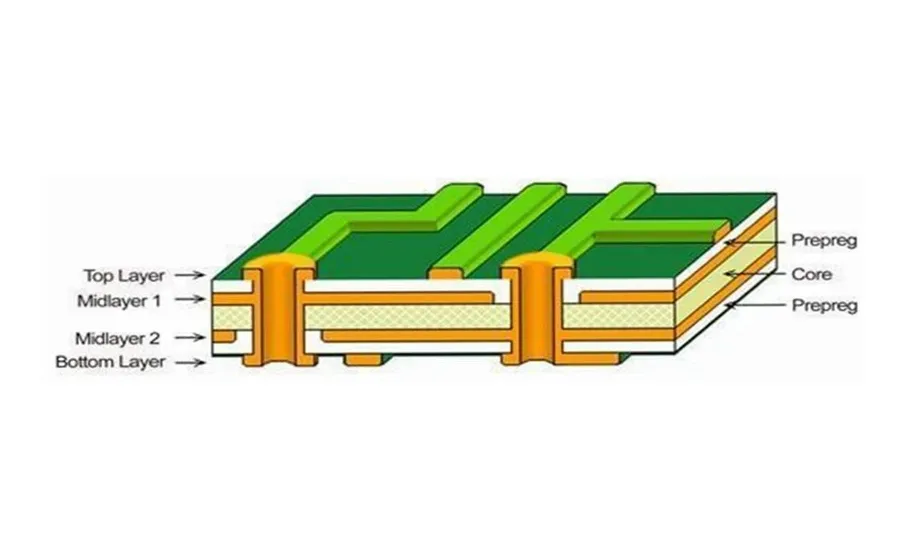
FR4 PCBs possess a combination of mechanical, electrical, thermal, and chemical properties that determine their suitability for various applications. These properties, resulting from the composite structure of fiberglass and epoxy resin, are critical for designers to consider when selecting FR4 for their printed circuit boards.
| Property | Typical Value | Significance |
|---|---|---|
| Tensile Strength | Typically 250-400 MPa | Measures the force required to break the material; indicates mechanical robustness. |
| Flexural Strength | Typically 350-500 MPa | Measures resistance to bending. Crucial for PCB handling and assembly. |
| Dielectric Constant (Dk) | Typically 4.2-4.8 @ 1MHz | Affects signal impedance; lower Dk is preferable for high-speed circuits. |
| Dissipation Factor (Df) | Typically 0.02 or less @ 1MHz | Measures signal loss; lower Df is ideal for high-frequency circuits. |
| Glass Transition Temperature (Tg) | Typically 130-180 °C (standard FR4), 170-210°C (high Tg) | The temperature at which the material begins to soften; higher Tg for higher temperature operations. |
| Thermal Conductivity | Typically 0.2 - 0.3 W/m·K | Measures the rate of heat transfer; lower conductivity can lead to heat accumulation. |
| Water Absorption | Typically 0.1 - 0.2 % | Indicates how much moisture the material absorbs over time. Affects dielectric properties and long-term stability. |
| Flammability Rating | UL94 V-0 | FR4 is self-extinguishing. Essential for fire safety. |
Understanding these properties allows designers to make informed decisions about material selection, particularly when it comes to balancing cost with performance requirements. Variations in these properties can exist based on the specific FR4 variant used, such as standard Tg versus high-Tg FR4, and it's critical to review the specific datasheets.
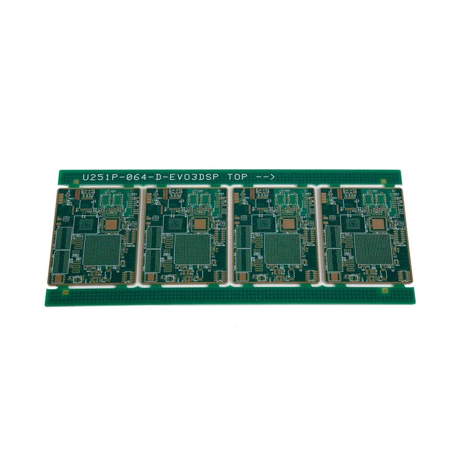
FR4's widespread adoption in PCB manufacturing stems from a combination of advantageous properties. Its versatility, cost-effectiveness, and balance of electrical and mechanical characteristics make it a staple material for a vast range of electronic applications.
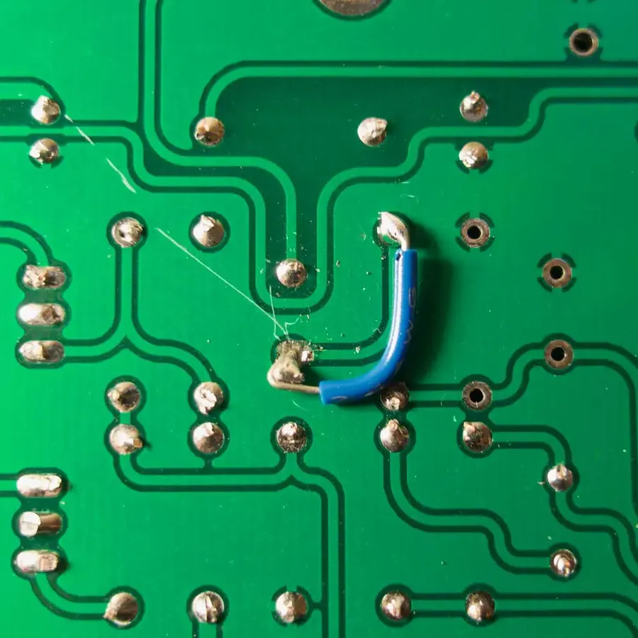
While FR4 is a ubiquitous and versatile material for printed circuit boards, it is crucial to acknowledge its limitations, especially when considering demanding applications. These limitations primarily revolve around its performance at high frequencies and temperatures, its moderate thermal conductivity, and its dimensional stability challenges.
At high frequencies, the dielectric constant and loss tangent of FR4 can become more prominent, leading to signal degradation. As frequency increases, the electrical properties of FR4 can lead to signal losses and impedance mismatches, which is particularly problematic for high-speed digital and RF applications. Furthermore, its moderate thermal conductivity can impede heat dissipation, particularly in high-power applications. This can lead to localized heating, potentially affecting performance and reliability of electronic components. Additionally, dimensional instability, mainly caused by fluctuations in temperature or humidity, can affect the performance and long-term reliability of the circuit. These limitations make FR4 less suitable for specific high-performance applications where more advanced materials are required.
| Limitation | Description | Impact on Performance | Potential Solutions |
|---|---|---|---|
| High-Frequency Limitations | Increased dielectric losses at higher frequencies. | Signal degradation, impedance mismatch. | Use materials with lower loss tangents like Rogers materials or more complex designs such as impedance controlled tracks. |
| Thermal Conductivity | Relatively low thermal conductivity compared to metal core PCBs | Heat build up, reduced component reliability | Employ heat sinks, metal cores, or thermal vias for improved heat dissipation. |
| Dimensional Instability | Expansion and contraction due to temperature and humidity. | Potential for warping and reduced long-term reliability. | Consider using higher-grade FR4 materials or incorporating specific design features to mitigate movement or to use other materials which are less susceptible to this |
| Temperature Limitations | Operational limitations in environments with extreme temperatures. | Reduced performance, component damage | Employ thermal management techniques or consider high-temperature laminates like polyimide. |
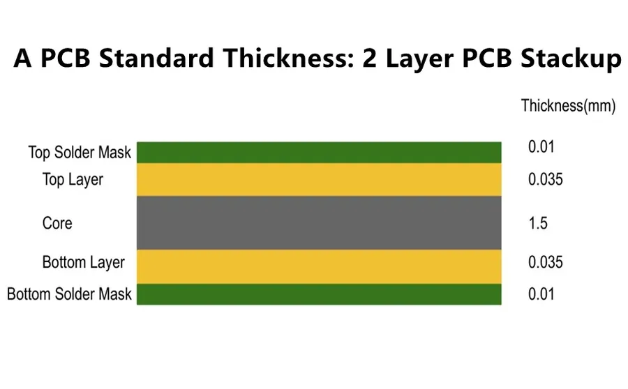
The thickness and layering of an FR4 PCB are critical design considerations that directly impact its performance, cost, and application suitability. Standard thicknesses offer flexibility for different project requirements, while layering techniques allow for complex circuit designs with optimized signal integrity and power distribution. This section delves into the typical thickness options and layering strategies for FR4 PCBs.
| Standard FR4 PCB Thickness | Typical Application | Pros | Cons |
|---|---|---|---|
| 0.2 mm (0.0079") | Flexible circuits, miniature devices | Lightweight, highly flexible | Fragile, not suitable for heavy components |
| 0.4 mm (0.016") | Small form factor devices, wearables | Thin and lightweight | Limited mechanical strength and not suitable for heavy components |
| 0.8 mm (0.031") | General-purpose electronics, portable devices | Good balance between flexibility and strength | Limited space for complex designs |
| 1.0 mm (0.039") | General-purpose electronics, portable devices | Good mechanical strength, adequate for most applications | Slightly less flexible than thinner options |
| 1.6 mm (0.063") | Standard thickness for most PCBs, industrial equipment | Robust, readily available, cost-effective | Can be bulky for small devices |
| 2.0 mm (0.079") and above | High-power applications, heavy-duty equipment | High strength, good heat dissipation | Higher cost, can be excessively bulky |
Beyond thickness, the layering of an FR4 PCB is fundamental to its functionality. The number of layers determines the complexity of the circuitry that can be accommodated. The most common configurations are single-layer, double-layer, and multi-layer PCBs.
| PCB Layer Type | Description | Advantages | Disadvantages |
|---|---|---|---|
| Single-Layer | Components and traces on one side of the board | Simple design, lowest cost, fastest manufacturing | Limited complexity, difficult routing of complex designs |
| Double-Layer | Components and traces on both sides of the board | Increased design flexibility, better component density | More complex than single-layer |
| Multi-Layer | Three or more layers of conductive traces separated by insulating layers | Highest complexity designs, high component density, optimized signal integrity, excellent power distribution | Most expensive, complex manufacturing |
The choice of PCB thickness and layering depends heavily on the application requirements. Thinner boards are often used in applications that prioritize weight and space, while thicker boards are used in applications requiring structural rigidity and high current carrying capacity. Layering is determined by the complexity of the circuit design. Single-layer boards are used for simple circuits; double-layer boards are employed for moderately complex circuits, and multi-layer boards are used in high-density circuits such as those found in advanced computing and communications equipment.
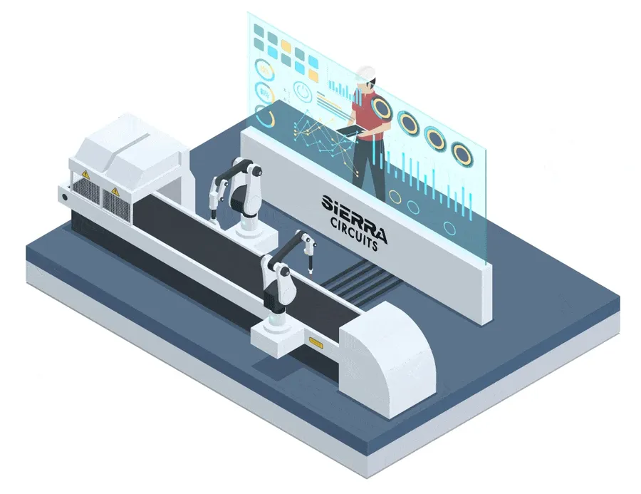
The transformation of raw FR4 material into a functional printed circuit board involves a series of precise manufacturing processes. These steps are critical to the performance and reliability of the final product, and understanding them is key for designers to make informed choices. The core processes encompass lamination, drilling, etching, and plating, each requiring specific controls and tolerances.
| Manufacturing Process | Description | Impact on Performance |
|---|---|---|
| Lamination | Multiple layers of FR4 material and copper foil are bonded together using heat and pressure. | Proper lamination ensures uniform dielectric properties and prevents delamination, which can cause circuit failures. |
| Drilling | Holes are created using precision drilling machines to accommodate vias and component leads. | Accurate drilling is vital for component placement and reliable inter-layer connections. Errors can cause misalignment and short circuits. |
| Etching | Unwanted copper is chemically removed to define the circuit traces and pads. | Precise etching is critical for achieving the desired trace widths and impedance control. Over-etching or under-etching can lead to performance issues. |
| Plating | A layer of metal (typically copper) is deposited onto the exposed copper surfaces to increase conductivity and provide a solderable finish. | Adequate plating ensures reliable electrical connections and solder joints. |
| Solder Mask Application | A protective layer of solder mask is applied to prevent short circuits and protect traces from environmental damage. | Solder mask accuracy is crucial to avoid exposing pads and preventing solder bridges |
| Silkscreen Printing | Text and symbols are printed on the board for component identification and assembly. | Clear silkscreen allows for proper assembly of the components and troubleshooting if issues arise. |
The interplay between these processes requires meticulous control and monitoring. Even slight variations can lead to significant differences in the final product. Choosing the correct manufacturing parameters, such as drilling speed, etching time, and plating thickness, directly impacts the performance and reliability of the board. Designers must work closely with manufacturers to ensure that the PCB meets all specifications.
Selecting the right PCB material is crucial for ensuring optimal performance and reliability in electronic devices. FR4 is a popular choice, but it's essential to understand how it stacks up against other materials like CEM-1, polyimide, and metal core PCBs. This section provides a detailed comparison, highlighting the strengths and weaknesses of each material across key parameters.
| Material | Cost | Thermal Conductivity | Dielectric Constant | Max Operating Temperature | Mechanical Strength | Typical Applications |
|---|---|---|---|---|---|---|
| FR4 | Low to Medium | Low (0.3 W/mK) | 4.5 | 130°C | Good | General-purpose PCBs, consumer electronics, most applications |
| CEM-1 | Low | Low | 4.2-4.8 | 110°C | Moderate | Single-sided PCBs, less demanding applications |
| Polyimide | High | Moderate (0.4-0.6 W/mK) | 3.5 | 260°C | Excellent | High-temperature applications, flexible circuits, aerospace |
| Metal Core (e.g., Aluminum) | Medium to High | High (up to 237 W/mK for Aluminum) | Variable (with dielectric layer) | Varies by dielectric layer, often >150°C | Good | LED lighting, power electronics, thermal management |
The table above provides a concise overview. Consider these aspects when selecting a material:
Ultimately, the best material is the one that best matches the needs of the application. Consider the trade-offs between cost, performance, and availability when making your selection. For many applications, FR4 offers a great balance of cost and performance, while other materials offer distinct advantages in specific situations.
This section addresses common questions and concerns regarding FR4 PCBs, providing concise and authoritative answers to help users make informed decisions about their application in electronic devices. We aim to clarify key aspects of FR4 material properties and usage.
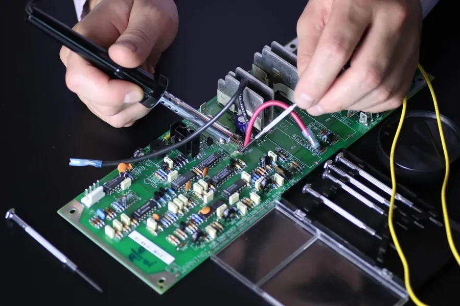
FR4 PCBs are ubiquitous in modern electronics due to their versatility, cost-effectiveness, and desirable properties. This section explores the broad spectrum of applications where FR4 PCBs are employed, highlighting their role across various industries.
In conclusion, FR4 PCBs are a versatile and reliable solution for a wide array of electronic applications. Their balance of cost-effectiveness, electrical insulation, and mechanical strength makes them a staple in the PCB industry. While not perfect for every situation, understanding the properties and limitations of FR4 helps engineers and designers make informed decisions, ensuring both performance and cost efficiency. This guide will serve as a comprehensive resource for navigating the complexities of FR4 PCB selection and implementation and further solidify its dominance in PCB fabrication.

