Mastering Feedthrough Capacitors: Design, Applications, and Selection Guide
2025.02.06
Imagine a bustling city where countless electronic signals crisscross, some carrying valuable data, others creating unwanted noise. Just like traffic lights direct vehicles, feedthrough capacitors guide signals, blocking unwanted high-frequency noise, thereby ensuring the smooth operation of electronic devices. This article delves into the intricacies of feedthrough capacitors, crucial components for maintaining signal integrity and reducing electromagnetic interference (EMI). We'll explore their working principles, applications, selection criteria, and comparisons to alternative filtering methods.
Understanding Feedthrough Capacitor Basics
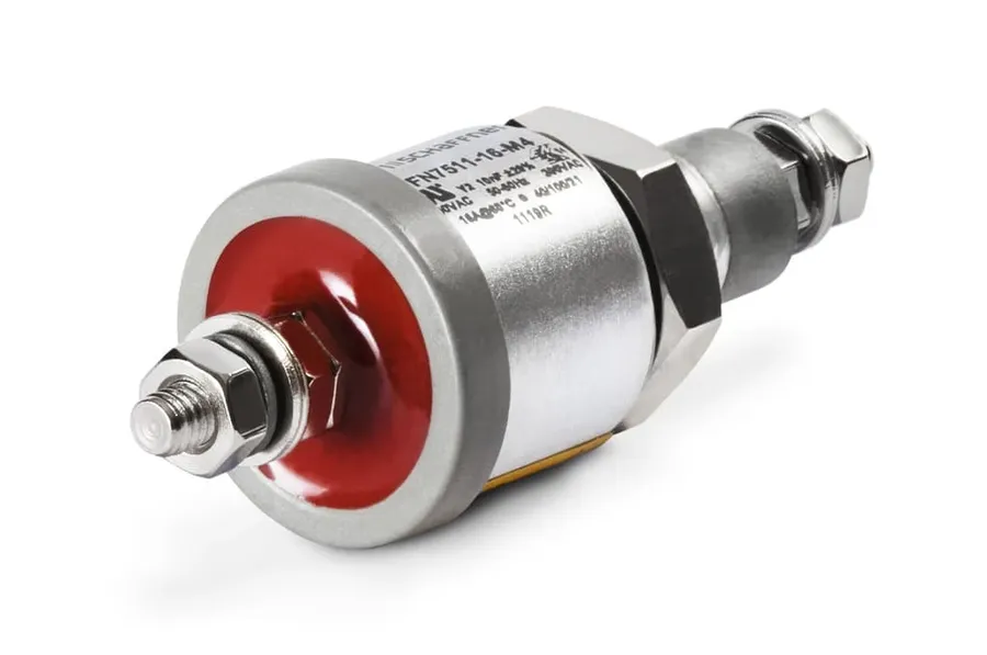
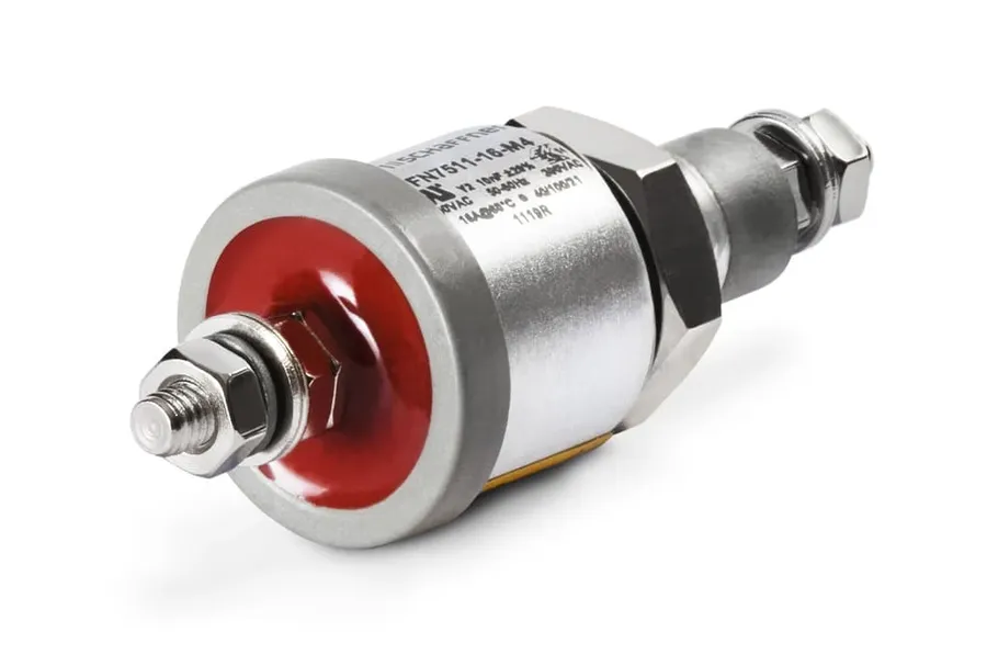
Feedthrough Capacitor
A feedthrough capacitor is a specialized three-terminal electronic component designed to suppress high-frequency electromagnetic interference (EMI). Unlike standard two-terminal capacitors, which are primarily used for energy storage or signal coupling, feedthrough capacitors are specifically constructed to allow a signal or power line to pass through while simultaneously shunting high-frequency noise to ground. This unique three-terminal configuration—with the input terminal, the output terminal, and the ground connection—is what sets feedthrough capacitors apart and makes them highly effective at reducing unwanted high-frequency noise in circuits and systems.
Feedthrough Capacitor Working Principles
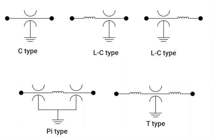
Feedthrough Capacitor Internal Structure
Feedthrough capacitors operate primarily as low-pass filters, strategically mitigating high-frequency electromagnetic interference (EMI) that can compromise the integrity of signals on power lines or signal paths. This functionality stems from their unique three-terminal design and the principle of capacitive coupling, allowing them to effectively attenuate unwanted noise.
At the heart of a feedthrough capacitor's operation is the concept of capacitive coupling. Unlike standard two-terminal capacitors which are placed in parallel or series, a feedthrough capacitor is designed to be physically integrated into a conductor path. The conductor carrying the electrical signal passes through the body of the capacitor where it is capacitively coupled to the capacitor's internal electrodes. This creates a low impedance path to ground for high-frequency noise, effectively shunting it away from the primary signal. Simultaneously, low frequency signals pass through with minimal impedance.
The effectiveness of a feedthrough capacitor as a low-pass filter arises from its capacitive reactance which is inversely proportional to the frequency of the signal. For high-frequency noise, the capacitive reactance is very low, allowing the noise to easily pass to ground. For low-frequency or DC signals the capacitive reactance is very high, effectively blocking the signal from being shunted to ground. This frequency-dependent behavior ensures that only the desired lower-frequency signals are allowed to proceed on the conductor, while high-frequency noise is effectively attenuated, thus improving the signal quality.
Feedthrough Capacitor Types and Construction
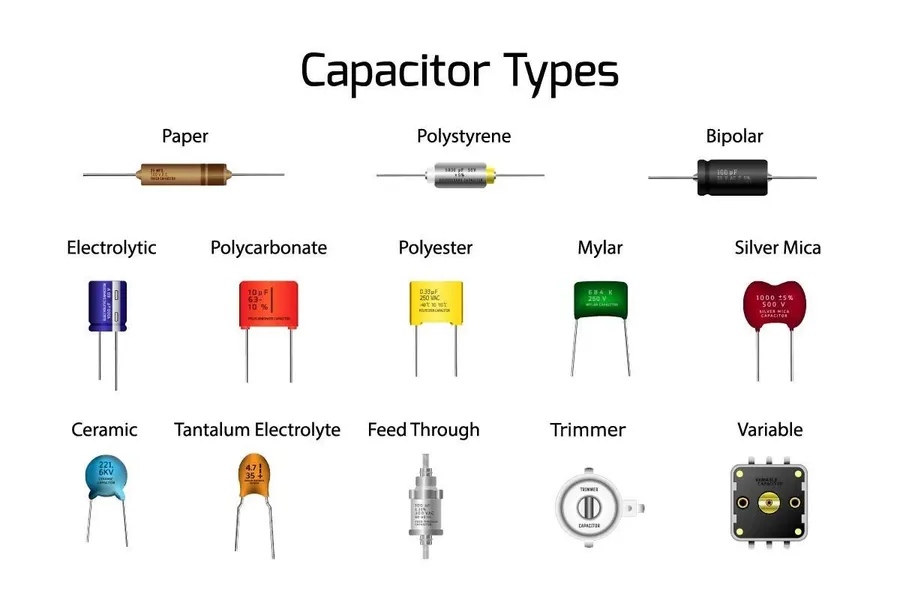
Various Feedthrough Capacitors
Feedthrough capacitors are available in a variety of types, each engineered to meet specific application requirements. These variations primarily stem from differences in construction, mounting style, and the dielectric materials used, all impacting their performance characteristics and suitability for various electromagnetic interference (EMI) suppression tasks.
The construction of a feedthrough capacitor fundamentally involves a conductive element (the 'feedthrough' itself) passing through a capacitive structure, typically a ceramic or other dielectric material. This design creates a low-impedance path for high-frequency noise to shunt to ground, while allowing the desired DC or low-frequency signals to pass through. The mechanical construction impacts physical size, mounting, and thermal performance.
Surface Mount Devices (SMD) Feedthrough Capacitors These capacitors are designed for automated assembly processes. SMD feedthrough capacitors are typically smaller than their through-hole counterparts and are mounted directly onto the surface of a printed circuit board (PCB). Their compact size makes them suitable for high-density applications where space is at a premium. SMD variations include chip capacitors and multi-layer ceramic capacitors (MLCC) that can offer high capacitance values in a small footprint.
Through-Hole Feedthrough Capacitors Through-hole feedthrough capacitors are designed to be inserted into plated through-holes on a PCB. They are generally more robust than SMDs but require more space on the board. They are often used in applications where the mechanical attachment needs to be especially strong or for high-voltage/high-current applications. These come in various package types, such as tubular and discoidal, depending on specific application demands.
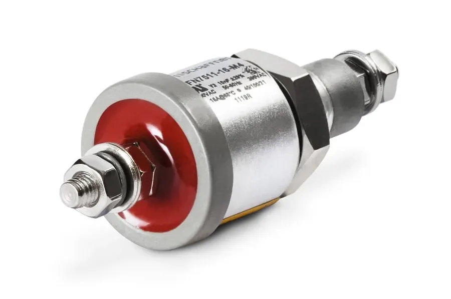
Bolt-in or Screw-in Feedthrough Capacitors Bolt-in or screw-in feedthrough capacitors are designed for chassis mounting. They usually have a threaded barrel that allows them to be firmly attached to a conductive panel, effectively grounding the capacitor's outer electrode. This type is often selected for very high power applications where robust mechanical connection and excellent grounding are essential for EMI shielding.
The dielectric material used within the feedthrough capacitor significantly influences its electrical performance, such as capacitance value, temperature stability, and operating frequency range. Common materials include:
Ceramic Dielectrics Ceramic materials, such as NP0/C0G, X7R, and Y5V, are frequently used due to their high dielectric constants, thermal stability, and relatively low cost. NP0/C0G ceramics offer excellent temperature stability and are preferred for precision applications, while X7R ceramics provide higher capacitance with some variation with temperature and voltage. Y5V ceramics have the highest capacitance but exhibit the most significant variations with operating conditions. MLCC (multi-layer ceramic capacitors) use these materials to achieve higher capacitance in small SMD packages.
Polymer Dielectrics Polymer dielectrics, like polyester and polypropylene, are also used, especially for applications where lower ESR (equivalent series resistance) and good high-frequency performance are needed but with lower temperature stability than ceramic options. These are often found in specialized higher voltage feedthrough capacitors and offer a range of options for specific applications.
Glass Dielectrics Glass dielectrics offer extremely low losses and high insulation resistance, making them suitable for high-reliability applications where these characteristics are critical. Glass is commonly used in high-frequency and high-temperature environments. Their robust construction makes them less susceptible to mechanical damage than polymer or ceramic options.
The selection of a feedthrough capacitor type is based on multiple factors, including mechanical requirements, available PCB space, the targeted frequency range for EMI suppression, voltage, and current ratings. Careful evaluation of all these criteria is vital to ensure optimum performance in any application.
Key Applications of Feedthrough Capacitors
Feedthrough Capacitors on PCB
Feedthrough capacitors are instrumental in mitigating electromagnetic interference (EMI) across a diverse range of applications. Their unique three-terminal design allows them to act as effective low-pass filters, shunting high-frequency noise to ground while allowing desired signals to pass. This characteristic makes them invaluable in scenarios where signal integrity and noise reduction are critical, ranging from shielding sensitive electronics to power supply regulation and RF systems.
Shielding Cases In electronic enclosures, feedthrough capacitors are used to filter noise that might enter or escape through the case. By mounting these capacitors on the conductive panel, they effectively suppress external EMI from interfering with internal circuits and vice versa. This is critical for meeting stringent electromagnetic compatibility (EMC) standards.
Power Supplies Feedthrough capacitors play a crucial role in power supplies by filtering high-frequency switching noise. They are placed at the input and output lines of power converters and regulators, reducing noise and improving overall power quality. This is essential for maintaining stable and efficient power delivery in many applications. These components are commonly employed in both linear and switching regulator circuits, contributing significantly to reducing both common-mode and differential-mode noise, which in turn aids in the reliable operation of a wide array of electronic systems.
RF Applications In radio frequency (RF) circuits, feedthrough capacitors help to filter spurious signals and harmonics. This is vital for maintaining a clean signal path and minimizing interference in communications equipment, radar systems, and other high-frequency applications. Additionally, the low inductance characteristic of feedthrough capacitors helps to stabilize the RF signal path, ensuring reliable and efficient signal transmission.
Medical Devices Medical devices often require low noise levels and reliable signal transmission, making feedthrough capacitors essential for EMI suppression in patient-connected equipment. They ensure the devices operate safely and without disruption, protecting delicate measurements and reducing the potential for inaccurate diagnoses or treatments. The reliability of these capacitors is particularly crucial given the sensitive nature of the application in human health.
Aerospace and Military Systems In the rigorous environments of aerospace and military applications, feedthrough capacitors are indispensable for their robustness and ability to perform reliably under extreme conditions. These applications require stringent EMI compliance, where feedthrough capacitors maintain the integrity of critical signals in high stress and variable conditions. This ensures that sensitive systems function effectively and without interference.
Selecting the Right Feedthrough Capacitor
Feedthrough Capacitor Installation
Selecting the appropriate feedthrough capacitor is crucial for effective EMI suppression and signal integrity. The selection process involves a careful evaluation of several key parameters to ensure the capacitor meets the specific requirements of the application.
Key parameters for selection include capacitance value, voltage rating, current rating, and operating frequency. Understanding the implications of each parameter is essential for making an informed decision. Over- or under-specification can lead to sub-optimal performance or unnecessary expense.
Capacitance Value The capacitance value determines the capacitor's ability to store charge and filter out specific frequencies. Higher capacitance values offer lower impedance at lower frequencies but may become less effective at higher frequencies due to parasitic inductance. Select a capacitance value that provides sufficient attenuation at the frequencies of concern. Typically, values range from a few picofarads (pF) to several microfarads (µF). Consult datasheets to verify the self-resonant frequency of the chosen capacitor to ensure adequate filter function at target frequencies.
Voltage Rating The voltage rating indicates the maximum voltage the capacitor can withstand without failure. Select a capacitor with a voltage rating that exceeds the maximum operating voltage in your application by a suitable safety margin, typically 20-50%. This prevents dielectric breakdown or long-term degradation of the capacitor, ensuring stable and reliable filter operation. Consider peak voltages as well as nominal levels when selecting the voltage rating.
Current Rating The current rating specifies the maximum current the capacitor can handle without overheating or damage. Excessive current flow can cause resistive heating, leading to premature failure. In applications with high current flow, choose a feedthrough capacitor with an adequate current rating with reference to the datasheet. This rating is influenced by the internal materials, design, and size of the capacitor. Derating current capacity for higher ambient temperatures is standard practice.
Operating Frequency The operating frequency range dictates the capacitor's effectiveness at various frequencies. Feedthrough capacitors are intended to attenuate high-frequency noise, so a capacitor with a self-resonant frequency above the frequencies of concern is desirable. Consider the impedance versus frequency curve on the product datasheet. Some capacitors have optimized designs for specific bands, such as MHz or GHz ranges. Select a capacitor that has minimal impedance at the target frequencies needing attenuation.
Temperature Characteristics Temperature characteristics are also a crucial part of the design. The operating temperature range and temperature coefficient must be appropriate for the application and environment. Capacitance often varies with temperature, and it must not excessively degrade at the expected operating temperatures.
Practical tips for selecting the right feedthrough capacitor include: starting with an analysis of the frequencies to be filtered, followed by detailed review of datasheets, considering potential sources of electromagnetic interference and following proper grounding techniques. Also, prototyping and testing are essential to validate the selection. Over-engineering can lead to unnecessary cost and space requirements, while under-engineering can compromise the performance.
Feedthrough Capacitor vs. Other Filtering Solutions
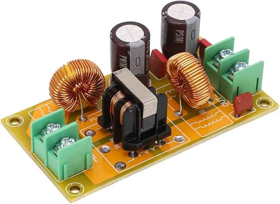
EMI Filters
Feedthrough capacitors are not the only components used for mitigating electromagnetic interference (EMI). Understanding their performance characteristics relative to other solutions like standard capacitors and ferrite beads is crucial for effective EMI management. Each component addresses specific filtering challenges and selecting the most appropriate solution is critical for optimal circuit performance.
Component
Mechanism
Pros
Cons
Typical Application
Feedthrough Capacitor
Capacitive coupling to a grounded conductor.
Effective for high-frequency noise, provides a direct path to ground, compact.
Can be more expensive, may have limited capacitance range compared to standard capacitors.
Shielded enclosures, power line filtering, RF signal lines.
Standard Capacitor
Capacitive impedance to AC signals.
Wide range of capacitance values, low cost, effective for bypassing and decoupling.
Less effective at high frequencies, noise can couple back into the circuit through lead inductance.
Power supply bypassing, signal decoupling, timing circuits.
Ferrite Bead
Inductive impedance to high frequency currents, resistive energy dissipation at resonance.
Simple to use, compact, effective at high frequency filtering.
Less effective at low frequencies, can introduce series resistance, may have a specific resonant frequency band.
Power supply lines, signal lines, noise suppression
Proper Installation and Wiring of Feedthrough Capacitors
Feedthrough Capacitor Wiring
Proper installation and wiring are paramount to realizing the full potential of feedthrough capacitors in EMI suppression. Incorrect techniques can negate their filtering effectiveness or, worse, introduce new problems. This section provides best practices for mounting and wiring feedthrough capacitors, focusing on soldering, grounding, and board layout considerations.
The performance of feedthrough capacitors is directly influenced by their installation. Unlike two-terminal capacitors where the parasitic inductance of the leads is part of the ESL (Equivalent Series Inductance), the three-terminal design of feedthrough capacitors requires careful mounting and wiring to preserve the low inductance through path. Key considerations include proper soldering, effective grounding, and correct board configurations.
Soldering Techniques Use appropriate soldering temperatures to avoid damaging the capacitor, usually below 260°C. Ensure that the soldering is done quickly to reduce the thermal stress. The goal is to achieve a smooth, shiny solder joint that provides a robust electrical connection without excessive solder.
Grounding Best Practices The grounding of the feedthrough capacitor is critical, as the body of the capacitor typically provides the ground connection to the enclosure. Ensure that the capacitor body has direct, low-impedance contact with the chassis or ground plane. This minimizes the return current loop and increases the filter effectiveness.
Board Configuration Considerations For optimal performance, the feedthrough capacitor should be mounted as close as possible to the entry point of the noise source into the shielded enclosure. The signal path that passes through the capacitor should also be as short and direct as possible to minimize parasitic inductance. If the ground plane is not readily accessible, it is best to extend the capacitor ground connection directly to the plane.
Avoiding Common Mistakes Avoid bending the capacitor leads as it can cause internal damage. Also, ensure that the chosen solder is appropriate for the capacitor termination material. Avoid over-tightening when mechanical connections are necessary, to prevent damage to the capacitor.
By adhering to these installation best practices, you can ensure that feedthrough capacitors perform as intended, significantly reducing EMI and safeguarding the integrity of your electronic systems.
Frequently Asked Questions About Feedthrough Capacitors
This section addresses common inquiries regarding feedthrough capacitors, providing clarity on their functionality, application, and differences when compared to other capacitive components. We aim to offer precise and technically sound answers to frequently asked questions.
What exactly are feedthrough capacitors? Feedthrough capacitors are three-terminal devices designed for EMI filtering applications. Unlike typical two-terminal capacitors, they are constructed to be mounted through a conductive barrier, thereby allowing signals to pass through while simultaneously filtering high-frequency noise. This characteristic is particularly useful in shielding cases and signal paths where it's crucial to minimize noise without interrupting signal flow.
What does 'feedthrough' mean in the context of RF applications? In RF contexts, 'feedthrough' refers to the method by which an electrical signal passes through a conductive barrier or enclosure. A feedthrough capacitor facilitates this passage while simultaneously providing a low-impedance path to ground for high-frequency noise, effectively filtering it out. This means that the desired signal is allowed to 'feedthrough', while unwanted RF noise is attenuated.
How do I correctly connect or wire a feedthrough capacitor? Proper connection of a feedthrough capacitor involves installing it through a conductive panel, ensuring that the conductive housing of the capacitor makes electrical contact with the panel. The input terminal of the signal is connected to one side of the capacitor, and the output is taken from the other side. The body of the capacitor is then grounded to the shielding case, which provides the necessary reference for the capacitance and establishes the low-impedance path for noise. Precision and proper grounding is vital for achieving optimal EMI filtering.
What distinguishes a feedthrough capacitor from a standard capacitor? The fundamental distinction lies in their physical construction and application. A standard two-terminal capacitor is primarily used for energy storage or as part of a timing circuit, where current flow is expected through the component. In contrast, a feedthrough capacitor is built for EMI filtering in a manner where a conductive barrier is used as a grounding point, and the capacitor is mounted through the barrier. This design difference creates a low-pass filter which allows DC and low-frequency AC signals to pass while attenuating high-frequency noise to ground.
What is the difference between a starter capacitor and a run capacitor, and does that apply to feedthrough capacitors? Starter and run capacitors are used in single-phase AC induction motors. Starter capacitors provide the initial high torque required to start the motor and are typically only used for short periods, they are also electrolytic. Run capacitors, conversely, are used continuously and are lower capacitance, and a usually non-electrolytic to improve lifespan and heat dissipation during constant use. Feedthrough capacitors, however, have no direct functional relationship to either, they are exclusively for EMI filtering purposes and work at much higher frequencies than those found in AC motors, typically. Thus the differences between starter and run capacitors do not apply to feedthrough capacitors because their purposes are different.
Are there specific wiring diagrams for feedthrough capacitors I should be aware of? Wiring diagrams for feedthrough capacitors generally highlight the importance of a solid ground connection to the metal panel or enclosure they are mounted on. The center pin passes through the case, with one end of the capacitor connected to the input signal line, and the other end to the output line. The body of the capacitor, is grounded to the metal panel it's mounted in. Each setup should be optimized to minimize impedance to ground, for the highest level of filtering.
Advanced Topics and Emerging Trends in Feedthrough Capacitor Technology
The field of feedthrough capacitor technology is continuously evolving, driven by the increasing demands for higher performance, miniaturization, and improved reliability in electronic devices. Advanced research focuses on enhancing high-frequency performance, exploring novel materials, and developing innovative designs to address emerging EMI challenges.
This section explores advanced concepts and emerging trends, providing insights into future directions within the domain of feedthrough capacitors.
High-Frequency Performance Optimization Advanced research aims to push the operational frequency of feedthrough capacitors into higher ranges (e.g., GHz). This involves designing components with minimal parasitic inductance and resistance, which can limit filtering effectiveness at very high frequencies. Techniques such as advanced material deposition and microfabrication are employed to achieve this.
Novel Materials Traditional ceramic dielectrics are being augmented and in some cases replaced by novel materials offering improved dielectric properties, temperature stability, and higher breakdown voltages. Examples include polymer-based dielectrics, nanocomposites, and thin-film materials, each tailored to specific application requirements and offering advantages like higher capacitance density or flexibility.
Miniaturization and Integration Driven by the demand for smaller electronic devices, there is a strong trend towards miniaturizing feedthrough capacitors. Surface mount devices (SMDs) are becoming increasingly common and more compact. Furthermore, efforts are being made to integrate feedthrough capacitor functionalities directly into circuit boards or connector assemblies, reducing space and assembly complexity.
Smart and Adaptive Capacitors Emerging technologies are exploring the integration of active elements, such as semiconductors, with feedthrough capacitors to create adaptive or tunable filtering devices. These could be dynamically adjusted to address specific EMI issues or to operate effectively across wide frequency bands. Such smart components will be particularly beneficial in complex systems or variable operational environments.
Environmental and Regulatory Compliance As environmental concerns grow, manufacturers are increasingly moving towards lead-free materials and sustainable manufacturing processes. New designs focus on materials that reduce environmental impact and satisfy increasingly stringent global regulations.
Advanced Testing and Characterization To ensure the reliability and performance of feedthrough capacitors, especially at higher frequencies, advanced testing and characterization methods are being developed. These include time domain reflectometry (TDR), vector network analysis (VNA), and specialized setups to analyze the devices' performance under different operational conditions.
Feedthrough capacitors, despite their simple design, play a vital role in the complex world of electronics. By mastering their principles, applications, and selection process, engineers can optimize system performance, reduce unwanted noise, and maintain signal integrity. The right choice of feedthrough capacitor acts like a guardian of signal fidelity, ensuring that your electronic systems operate smoothly and efficiently in a world filled with electromagnetic interference. As technology evolves, so do these tiny components, promising even greater performance and new opportunities to manage EMI in the future.