In the intricate world of electronics, the humble PCB (Printed Circuit Board) serves as the foundation for countless devices. The method of mounting components onto these boards – particularly switches, connectors, and stabilizers – significantly impacts performance and stability. Just as the right foundation is key to a strong building, the proper PCB mount is essential for reliable electronic devices. This article will delve into the world of PCB mounts, exploring their types, differences, and how to choose the right one for your specific needs.
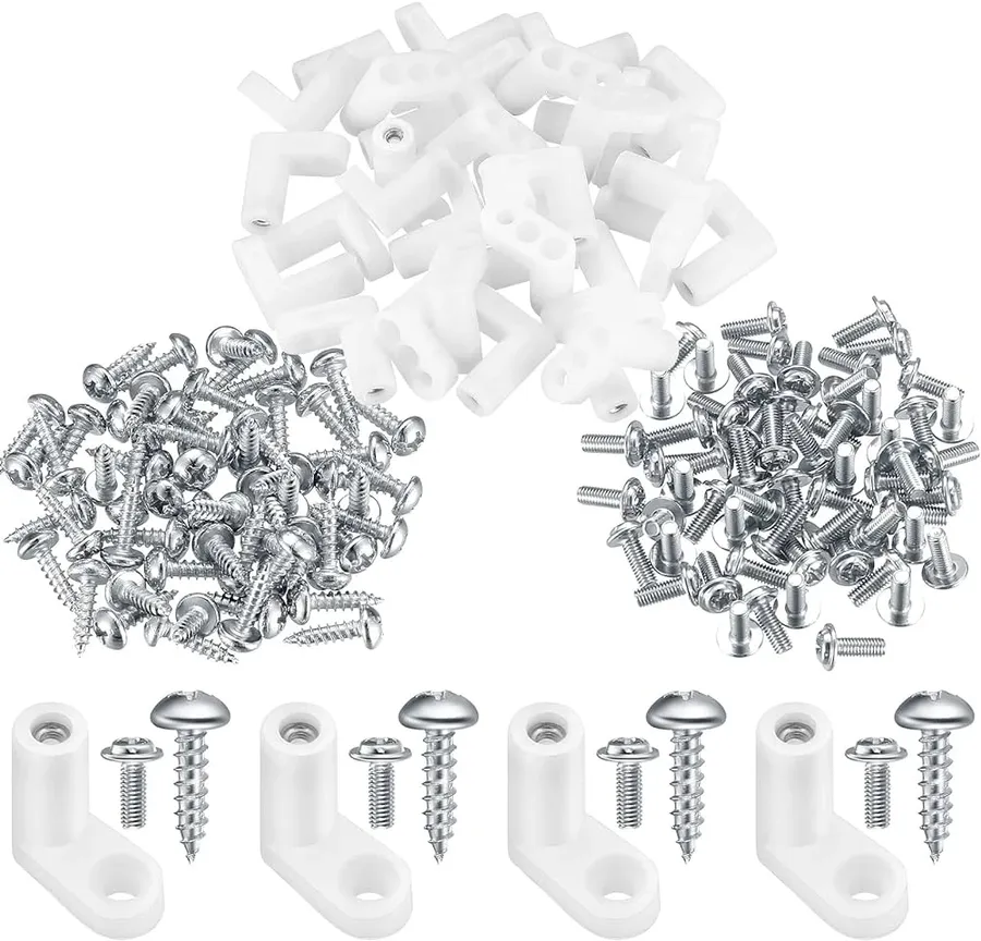
PCB mounting, at its core, refers to the method by which electronic components are physically attached and electrically connected to a Printed Circuit Board (PCB). This process is fundamental to electronics manufacturing, as it establishes the mechanical and electrical integrity of a device. The choice of mounting method significantly impacts the performance, reliability, and assembly process of electronic devices. Selecting the appropriate mounting technique ensures that components are securely held in place, withstand mechanical stresses and vibrations, and make reliable electrical contact. This foundational understanding is critical for subsequent discussions on specific mounting types, such as PCB mount and plate mount methods.
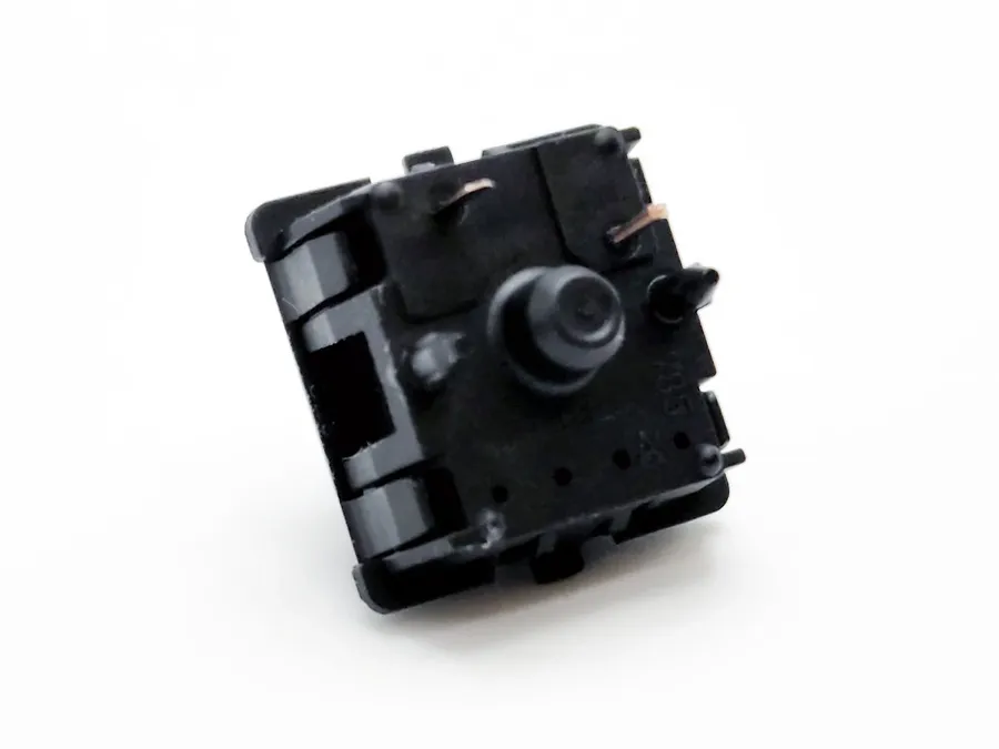
The fundamental distinction between PCB mount and plate mount lies in how components, particularly switches and connectors, are affixed to a printed circuit board (PCB). This difference significantly impacts mechanical stability, design complexity, and overall user experience, especially in applications like mechanical keyboards. PCB mount components directly attach to the PCB, while plate mount components use an intermediary plate for support.
| Feature | PCB Mount | Plate Mount |
|---|---|---|
| Mounting Method | Directly soldered to PCB | Mounted to a plate, then plate is attached to PCB or case |
| Number of Pins (typical for switches) | 5 pins | 3 pins |
| Mechanical Stability | Generally higher stability due to direct connection | Stability depends on plate material and mounting |
| Switch Replacement | Requires desoldering for switch replacement | Potentially easier switch replacement, hot-swappable option possible |
| Design Considerations | More complex PCB design to accommodate direct soldering and alignment pins | Simpler PCB design; relies on plate for component support and alignment. |
| Typing Feel | Typically more solid and less likely to flex | Flexibility can vary depending on the plate, potentially leads to softer feel |
| Cost | Potentially higher due to PCB complexity | Potentially lower due to simpler PCB |
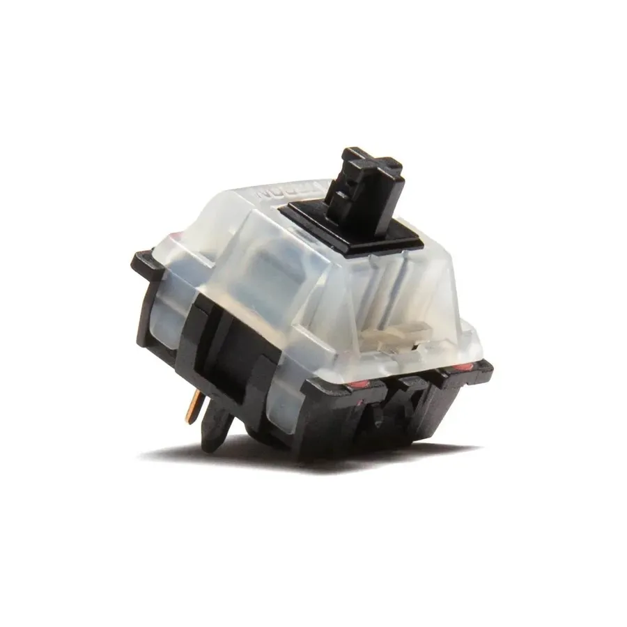
PCB mount switches are designed for direct soldering onto a printed circuit board (PCB), providing a secure and stable connection. This method is particularly prevalent in mechanical keyboards where durability and consistent key feel are paramount. The direct soldering approach not only enhances mechanical integrity but also contributes significantly to the overall user experience, ensuring reliable operation and a solid feel with each keystroke.
Unlike plate-mounted switches that rely on a supporting plate, PCB mount switches interface directly with the PCB. This difference in mounting has several key implications:
| Feature | PCB Mount Switches | Plate Mount Switches |
|---|---|---|
| Mounting Method | Directly soldered to PCB | Mounted to a supporting plate |
| Pin Count | 5 pins (2 electrical, 3 alignment) | 3 pins (2 electrical, 1 optional alignment) |
| Stability | Higher, due to direct soldering and extra pins | Lower, dependent on plate and switch design |
| Typing Feel | Firmer, more direct | Can be softer, less direct |
| Applications | Mechanical keyboards and projects requiring high stability and consistency | Common in hot-swappable keyboards and general electronic projects |
The additional alignment pins on PCB mount switches are crucial for ensuring each switch is perfectly aligned on the board during soldering. This precise alignment contributes to a uniform typing experience across the entire keyboard, reducing inconsistencies and increasing overall reliability. In summary, PCB mount switches are a great option for users who value a stable and consistent feel in their keyboards and other electronic projects.
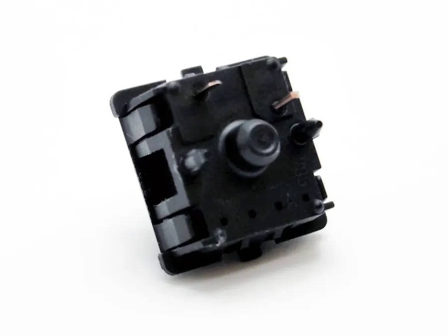
Plate-mounted switches utilize a metal plate, typically steel or aluminum, to provide support and structural integrity to the switches. This mounting method is particularly favored when ease of switch replacement and hot-swappable functionality are desired.
The plate acts as an intermediary layer between the switch and the PCB, creating a different feel and sound profile compared to direct PCB mounting. Plate mounting offers benefits in terms of modularity and repairability, which contrasts with the more permanent nature of PCB-mounted switches.
| Feature | Plate Mount Switches | PCB Mount Switches |
|---|---|---|
| Support Structure | Metal Plate | Directly to PCB |
| Number of Pins | 3 pins | 3 or 5 pins |
| Stability | Good, dependent on plate rigidity | Excellent, soldered directly |
| Ease of Replacement | High (especially with hot-swap) | Low (requires desoldering) |
| Ideal Use Cases | Hot-swappable keyboards, where switch variety is desired | Keyboards where high stability and permanent installation is preferred |
Specifically, plate-mounted switches excel in scenarios where the user might want to easily experiment with different switch types without the need for soldering equipment, or when switch replacement is a likely maintenance requirement.
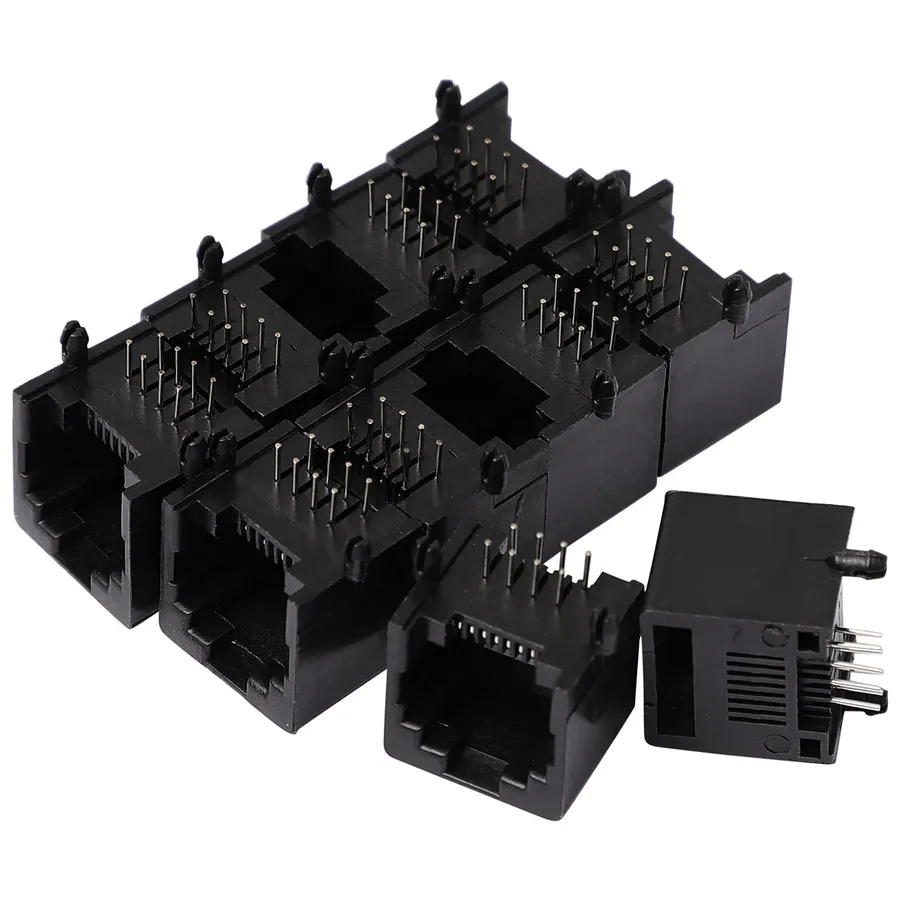
PCB mount connectors are essential components for establishing electrical connections directly on a printed circuit board (PCB). These connectors facilitate the transfer of power and signals between the PCB and other components or external devices, ensuring reliable and robust electronic systems. The selection of appropriate PCB mount connectors is crucial for the performance and longevity of electronic products.
| Connector Type | Description | Typical Applications | Mounting Style |
|---|---|---|---|
| Headers | Provide pin-to-pin connections using male and female pins. Available in various pitches and configurations, such as straight, right-angle, and shrouded headers. | Inter-board connections, wire-to-board connections, programming interfaces. | Through-hole, Surface Mount (SMT) |
| Terminal Blocks | Allow for secure, screw-down connections for wires to PCBs, often used for power or high-current signal transfer. | Power distribution, motor control, sensors. | Through-hole, Surface Mount (SMT) |
| Edge Connectors | Connect along the edge of the PCB, often used for daughterboards and card slots. | Expansion cards, memory modules, PCI slots. | Edge-mount |
| Board-to-Board Connectors | Designed to connect two or more PCBs together, often utilizing fine-pitch pins for high-density interconnections. | Stacking PCBs, modular electronics | Surface Mount (SMT) |
| Enclosure Connectors | Specifically designed to mount to enclosures and provide I/O connections, such as USB, Ethernet, and audio jacks. | External connectivity for devices, panel mounting. | Panel mount, Through-hole |
| Wire-to-Board Connectors | Used to connect individual wires to a PCB. This category includes IDC (Insulation Displacement Connectors) and crimp connectors. | Power supplies, signal routing, peripheral connections. | Through-hole, Surface Mount (SMT), IDC |
The choice of PCB mount connector is influenced by factors such as signal type (power, data, analog), current and voltage requirements, frequency, mechanical stresses, environmental conditions, and ease of assembly. Industry standards such as IPC (Association Connecting Electronics Industries) provide guidelines for connector selection and assembly to ensure reliability and interoperability.
In practice, PCB mount connectors are used in a broad spectrum of applications, ranging from consumer electronics like smartphones and laptops to industrial equipment, automotive systems, and aerospace technology. Proper selection and implementation of these connectors are critical for maintaining the functionality and durability of electronic devices.
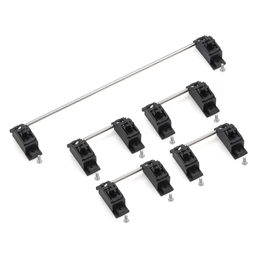
PCB mount stabilizers are crucial components in mechanical keyboards, specifically designed to enhance the stability of larger keys, such as the Shift, Enter, Spacebar, and Backspace keys. These stabilizers directly attach to the printed circuit board (PCB), providing a solid foundation that minimizes wobble and ensures consistent key presses. Unlike their plate-mounted counterparts, PCB mount stabilizers contribute to a more uniform and refined typing experience, affecting both the feel and the sound of these frequently used keys.
| Feature | PCB Mount Stabilizers | Plate Mount Stabilizers |
|---|---|---|
| Mounting | Directly to the PCB | To the keyboard's mounting plate |
| Stability | Higher, less wobble | Can have slight wobble |
| Sound | Generally deeper, less rattle | May produce more noise |
| Complexity | More involved installation | Easier to install/remove |
Modifying or converting between PCB mount and plate mount components, particularly switches, presents unique challenges and opportunities for DIY enthusiasts. While not always straightforward, understanding the nuances of each mounting type allows for informed decisions about potential modifications.
Generally, PCB mount components, known for their direct soldering to the PCB and alignment pins, can be adapted for plate mounting with some adjustments. However, converting plate mount switches for PCB mounting is more complex because they lack alignment pins.
| Feature | PCB Mount to Plate Mount | Plate Mount to PCB Mount |
|---|---|---|
| Pin Configuration | Typically 5 pins; can often be modified for 3-pin plate mounting. | Typically 3 pins; no alignment pins for direct PCB mounting. |
| Modification Difficulty | Relatively easier, often involves clipping or removing alignment pins. | Significantly more difficult, requires adding stabilizing elements. |
| Mechanical Stability | Reduced; relies on plate and switch fit, less stable than direct soldering. | Requires additional measures for stability. |
| Feasibility | More feasible with standard components, but depends on the case design. | Less feasible, as it needs structural changes and is not easily achievable. |
| Considerations | Check for proper alignment and switch fit within the plate. | Will likely require 3D-printed parts or custom solutions to ensure secure connections to the PCB. |
It's important to consider the structural integrity of the converted components and the overall mechanical properties of the setup. Always take precise measurements and handle modifications carefully to avoid permanent damage.
This section addresses common queries regarding PCB mounts, providing clear and concise answers to help you better understand this essential aspect of electronics assembly. We'll cover definitions, comparisons, and applications.
Selecting the appropriate PCB mount is crucial for any electronics project, directly impacting performance, stability, and cost. The optimal choice hinges on a careful evaluation of project requirements, budget constraints, and desired performance characteristics. This section offers a comparative analysis to guide your selection process.
| Feature | PCB Mount | Plate Mount |
|---|---|---|
| Mechanical Stability | Directly soldered to PCB for enhanced rigidity and stability. | Relies on a plate for support, can be less stable compared to PCB mount. |
| Pin Count | Typically 5 pins for additional support and alignment. | Typically 3 pins; two for signal and one for mechanical support. |
| Cost | Can be more cost-effective due to fewer separate parts but may require more precise soldering. | May incur higher cost because of the additional plate component but simplifies the assembly process. |
| Ease of Replacement | More challenging to replace due to direct soldering. More suited for fixed, less flexible designs. | Easier to replace with the assistance of a plate, often compatible with hot-swappable solutions. |
| Applications | Optimal for high-performance, fixed applications where stability is critical, common in mechanical keyboards and durable equipment. | Preferred for customizable, modular, and flexible projects that require ease of switch swapping or where a more easily assembled construction is preferred, common in hobbyist projects and mass-market electronics. |
| Assembly Requirements | Demands a high degree of soldering accuracy, typically used in systems with pre-assembled circuit boards. Precision in component placement is key. | Can facilitate easier initial assembly, especially for designs needing flexibility and alterations and component position is less critical because the plate provides a physical guide. |
When choosing a PCB mount, consider the following: For high stability and permanent installations, PCB mounts are ideal. If you anticipate frequent adjustments or replacements, a plate mount is more appropriate. Assess not only the technical aspects but also the project budget and your own skill level in component assembly.
Selecting the correct method of mounting components on your PCB, especially choosing between PCB mount and plate mount options, is crucial for creating robust, reliable, and effective electronic devices. By understanding the nuances of each method for switches, connectors, and stabilizers, designers can optimize their projects for stability and functionality. Whether you are building a high-end mechanical keyboard or another circuit board, a solid understanding of PCB mount techniques will be a valuable asset for your next electronics project.

