
As the automotive industry pivots toward Level 4 and Level 5 autonomous driving, the humble Electric Power Steering (EPS) system is undergoing a massive architectural transformation. No longer just a convenience feature, steering is now a critical safety node that demands unprecedented levels of resilience. In this analysis, we examine how next-generation PCB architectures are moving beyond traditional control modules to enable a future where safety and reliability are non-negotiable.
The Evolution of Steering: From Mechanical to Smart Electronic Control
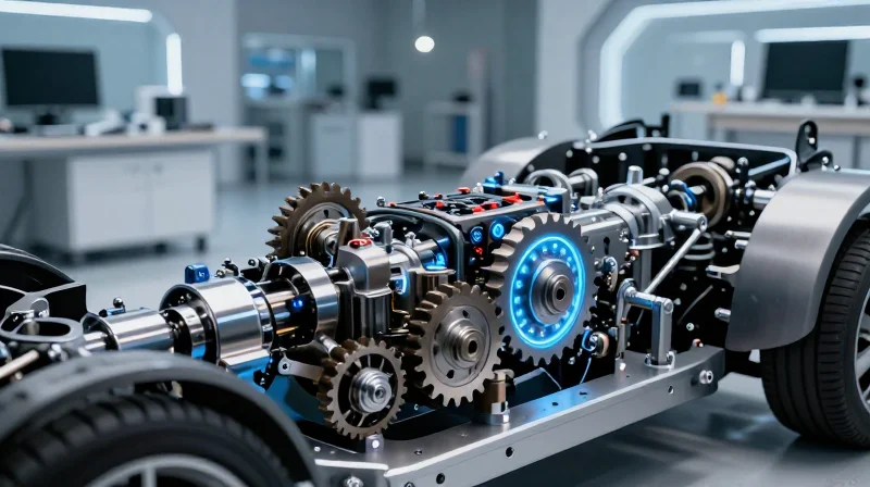
The Trajectory of Steering Innovation
The journey of steering technology began with simple rack-and-pinion mechanical linkages, evolved into hydraulic power-assist systems, and has now matured into advanced EPS. Unlike legacy hydraulic systems that rely on engine-driven pumps, modern EPS utilizes an electric motor to provide assistance, significantly improving fuel efficiency and reducing mechanical complexity. This transition has enabled the integration of electronic control units (ECUs) directly into the steering rack, transforming the steering system from a mechanical peripheral into an active participant in vehicle dynamics.
Technological Milestones in Steering Development
| Era | Technology | Control Driver |
|---|---|---|
| Pre-1950s | Purely Mechanical | Driver Strength |
| 1950s-2000s | Hydraulic Assist | Engine-driven pump |
| 2000s-2015 | Early EPS | Simple ECU Logic |
| 2015-Present | Smart EPS/Steer-by-Wire | Autonomous Integration |
Integration with ADAS and Autonomous Platforms
Modern EPS serves as a critical actuator for Advanced Driver Assistance Systems (ADAS). By digitizing steering inputs, manufacturers can implement features such as lane-keeping assist, automated parking, and collision avoidance through corrective steering maneuvers. In autonomous vehicles, this integration reaches its zenith, where the steering rack is no longer just responding to a steering wheel, but is capable of processing sensory input from LiDAR and radar to navigate complex environments without human intervention.
Frequently Asked Questions
- Why was EPS chosen over traditional hydraulic steering?
EPS eliminates parasitic loss caused by engine-driven pumps, improves fuel efficiency, and allows for software-level adjustments to steering feel and precision. - How does PCB technology impact steering reliability?
Advanced PCB designs allow for redundant processing and high-temperature tolerance, ensuring that the steering system remains functional even if a primary component suffers a transient failure. - What role does Steer-by-Wire play in future vehicle architectures?
Steer-by-Wire completely decouples the steering wheel from the mechanical rack, enabling variable steering ratios and freeing up physical space for interior cabin redesigns in autonomous platforms.
PCB Architecture Requirements for High-Availability Systems
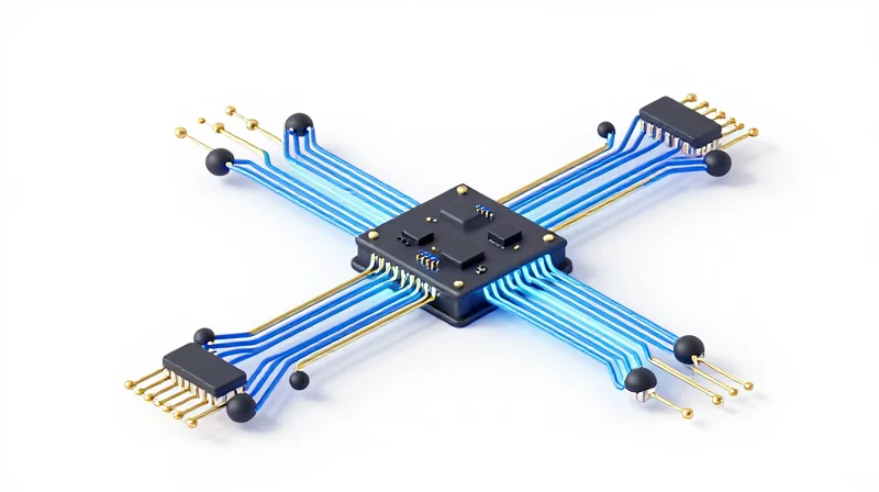
The Necessity of Redundancy in EPS Architecture
In fully autonomous vehicles, the Electric Power Steering (EPS) system is classified as a safety-critical component, meaning any single point of failure can lead to catastrophic loss of control. Modern architecture demands dual-wound motors and independent power stages to ensure functional safety, often aligning with ISO 26262 ASIL-D requirements. PCB design must prioritize thermal management and electrical isolation between these redundant channels to prevent common-cause failures.
Comparing Conventional vs. High-Availability PCB Layouts
| Feature | Conventional EPS | Autonomous-Ready EPS |
|---|---|---|
| Power Path | Single Feed | Dual Redundant |
| Microcontroller | Single Logic Unit | Dual-Lockstep/Multi-Core |
| PCB Material | Standard FR-4 | High-Tg / Metal Core |
| Failure Mode | System Shutdown | Degraded Performance (Fail-Operational) |
Critical PCB Design Strategies for Reliability
To achieve the required level of safety, PCB designers must go beyond simple routing. Implementation of 'Safe-State' logic ensures that in the event of a bus communication error, the EPS remains in a state that allows the vehicle to pull over safely. Key design elements include:
- Galvanic Isolation
Utilizing advanced digital isolators on the PCB prevents voltage spikes or short circuits from propagating across redundant logic channels. - Thermal Partitioning
Placement of power MOSFETs is optimized using thermal relief patterns to avoid heat soaking the sensitive control logic during peak steering loads. - Redundant Power Rails
Incorporating separate power supply inputs (KL30/KL31 redundancy) ensures that the system remains powered even if a primary fuse or harness connector fails.
FAQ: EPS PCB Architecture
- How does ASIL-D compliance affect PCB complexity?
It mandates hardware redundancy, error-correcting code (ECC) memory, and continuous diagnostic circuitry, significantly increasing layer counts and routing density. - Why is metal core PCB becoming standard in EPS?
As steering motors draw higher currents in electric vehicles, metal core boards provide superior thermal conductivity to dissipate heat generated by the high-power inverter stages.
Traditional Control Modules vs. Next-Gen Power Electronics
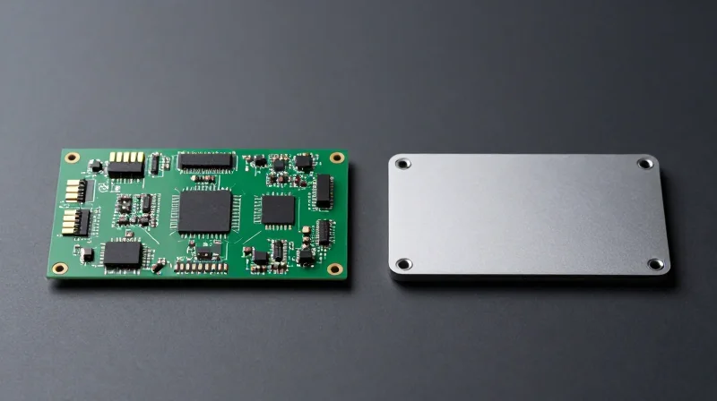
From Legacy Control Modules to High-Performance Power Electronics
The transition from traditional Electronic Control Units (ECUs) to next-generation power electronics represents a paradigm shift in how EPS systems manage energy and reliability. Legacy modules, often limited by silicon-based MOSFETs and standard FR4 PCB substrates, struggled with the thermal dissipation required for the high-current demands of steer-by-wire and autonomous systems. Modern power electronics leverage wide-bandgap semiconductors—specifically Silicon Carbide (SiC) and Gallium Nitride (GaN)—paired with advanced substrate technologies to achieve greater efficiency, faster switching frequencies, and significantly reduced thermal footprints.
| Feature | Legacy Control Modules | Next-Gen Power Electronics |
|---|---|---|
| Semiconductor Material | Standard Silicon (Si) | SiC / GaN |
| Switching Frequency | Low (10-20 kHz) | High (>100 kHz) |
| Thermal Management | Bulky Heat Sinks | Integrated Thermal Vias / Ceramic PCBs |
| Efficiency | Moderate | Ultra-High |
| System Size | Large, Distributed | Compact, Integrated |
Key Advantages of Next-Generation Architectures
Next-gen architectures prioritize modularity and density. By integrating power stages directly onto the EPS motor housing, engineers minimize electromagnetic interference (EMI) and latency. This transition is not merely about size; it is about enabling the high-bandwidth communication necessary for autonomous vehicle (AV) reaction speeds.
- Why are wide-bandgap materials critical?
Materials like GaN allow for higher voltage operation and faster switching, which drastically reduces the size of passive components like inductors and capacitors. - How does PCB substrate affect reliability?
Modern ceramic or metal-core PCBs offer superior thermal conductivity compared to legacy FR4, preventing degradation in power transistors during sustained high-torque steering maneuvers. - What role do integrated sensors play?
Next-gen modules integrate sensing directly into the power path, allowing for real-time diagnostics and predictive maintenance, a requirement for ISO 26262 functional safety compliance.
The Role of Thermal Management in High-Density PCB Design
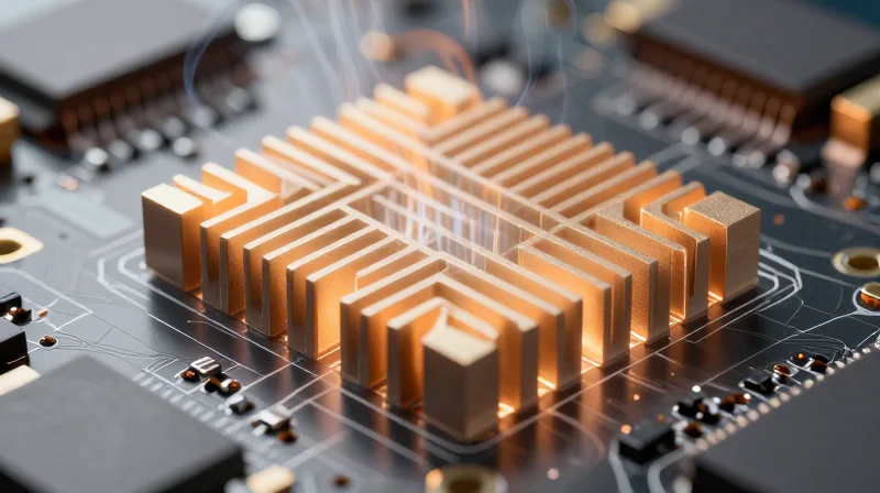
The Thermal Challenge in High-Density EPS Modules
As Electronic Power Steering (EPS) modules transition to smaller form factors, the power density of onboard electronics increases exponentially. The concentration of high-current MOSFETs and microprocessors on compact PCBs creates localized heat zones that can compromise solder joint integrity and accelerate dielectric degradation. Effective thermal management is no longer an optional add-on but a fundamental design constraint that dictates the lifespan and safety performance of autonomous-grade steering systems.
Heat Dissipation Techniques Comparison
| Technique | Primary Mechanism | Application Suitability |
|---|---|---|
| Thermal Vias | Conduction to inner layers/heatsink | High-density signal/logic clusters |
| Metal-Core PCBs (MCPCB) | Dissipation through aluminum base | High-current power stages |
| Phase Change Materials | Thermal resistance reduction | Hot-spot mitigation for processors |
Critical Factors in Thermal Design
- How does PCB substrate selection impact heat flow?
Modern EPS modules utilize high-Tg (Glass Transition Temperature) FR-4 or ceramic substrates to maintain structural integrity during prolonged thermal cycling, preventing delamination at high operating temperatures. - Why is copper weight vital for thermal management?
Increasing the weight of internal copper planes serves a dual purpose: it lowers electrical resistance in high-current paths and acts as a significant thermal spreader to distribute heat away from localized hotspots. - What is the role of simulation in thermal design?
Computational Fluid Dynamics (CFD) and FEA modeling are essential to identify potential failure points before physical prototyping, allowing engineers to optimize the placement of components relative to airflow and heat dissipation surfaces.
Ultimately, the longevity of EPS electronics relies on minimizing the 'junction-to-case' thermal resistance. By integrating advanced thermal management strategies early in the layout phase, designers can ensure that autonomous steering systems remain operational throughout the vehicle's lifespan, even under the rigorous demands of continuous performance monitoring and fail-safe execution.
Materials and Manufacturing: Driving Resilience in Harsh Automotive Environments
Substrate Engineering for Extreme Durability
In the context of EPS, standard FR-4 substrates often fail to meet the thermal and vibrational demands of chassis-mounted electronics. Engineers are increasingly pivoting toward High-Tg (glass transition temperature) laminates and ceramic-filled substrates to mitigate micro-cracking and signal degradation. These materials offer superior dimensional stability, ensuring that high-speed sensor data remains consistent even when subjected to the intense mechanical fatigue of a steering rack.
| Material Type | Key Advantage | EPS Application |
|---|---|---|
| High-Tg FR-4 | Thermal stability | General Control Units |
| Metal-Core PCB (MCPCB) | Superior heat transfer | Power Inverters |
| Polyimide-based Flex | Vibration resistance | Steering Column Sensors |
Manufacturing Advancements and Environmental Protection
Manufacturing processes for EPS boards have evolved beyond simple surface-mount assembly. Conformal coating automation and pressurized potting techniques are now the industry standard for creating moisture-proof barriers. Furthermore, the integration of advanced shielding materials—such as conductive gaskets and vapor-deposited EMI shielding layers—directly onto the PCB assembly is essential to prevent signal interference in the electromagnetically dense environment of an electric vehicle's powertrain.
Frequently Asked Questions on EPS Reliability
- Why is moisture ingress a primary failure mode for EPS?
Steering modules are often located in exposed areas under the vehicle chassis. Without advanced encapsulation and humidity-resistant substrates, moisture leads to dendrite formation and localized short-circuiting. - How does vibration affect high-density PCB connections?
Continuous mechanical vibration can cause fatigue in solder joints. Utilizing underfill materials beneath CSP (Chip Scale Packages) significantly reinforces these connections, extending the operational lifespan of the EPS controller. - Is EMI shielding becoming more difficult in modern vehicles?
Yes, with the increasing density of high-voltage cabling and wireless communication modules in autonomous vehicles, PCBs require more robust, integrated EMI containment solutions to maintain the integrity of steer-by-wire signaling.
Functional Safety Standards: ISO 26262 and PCB Compliance
ISO 26262 and Automotive Safety Integrity Levels (ASIL)
ISO 26262 defines the lifecycle for automotive safety-critical systems, mandating a risk-based approach to hazard assessment. For EPS systems, which directly influence vehicle path control, design teams typically target ASIL D, the highest integrity level, due to the critical nature of potential steering failures. Achieving this requires strict adherence to hardware development lifecycles, fault detection mechanisms, and comprehensive failure mode analysis (FMEA) throughout the PCB design process.
PCB Design Strategies for Functional Safety
Designing for functional safety within the PCB architecture requires hardware redundancy, diagnostic coverage, and strict isolation protocols. To comply with ASIL D requirements, designers must implement strategies that mitigate common-cause failures.
| Design Strategy | Purpose | Safety Impact |
|---|---|---|
| Component Redundancy | Dual-path circuits | Eliminates single points of failure. |
| Galvanic Isolation | Separates control/power | Prevents high-voltage transient propagation. |
| Diagnostics (BIST) | Built-in Self-Test | Monitors health in real-time. |
| Layout Partitioning | Segregating traces | Prevents cross-talk and physical interference. |
Compliance and Verification Challenges
- How does PCB layout impact ISO 26262 certification?
Layout decisions determine fault tolerance; improper routing or thermal management can lead to unforeseen failure modes that invalidate safety analysis. - What is the role of traceability in PCB manufacturing?
Full traceability is mandatory, from raw material batch logs to final functional test data, ensuring every component meets the documented safety standards. - Does higher component density increase ASIL complexity?
Yes, high-density interconnections (HDI) increase the potential for signal integrity issues and thermal cross-talk, making it harder to prove physical isolation between safety channels.
Ultimately, compliance is not just about documentation; it is about building physical resilience into the PCB. As EPS systems evolve towards fully autonomous operations, the integration of safety-conscious design—such as advanced fault-monitoring circuits and robust manufacturing quality control—remains the foundation for building trustworthy, fail-operational steering architectures.
Connectivity and Edge Processing within the Steering Node

Architectural Evolution: From Actuation to Edge Intelligence
The transition to steer-by-wire (SbW) architectures requires the steering node to function as a sophisticated edge processor. Modern steering PCBs no longer simply interpret input signals; they now host localized high-performance SoCs (System-on-Chips) that perform real-time sensor fusion and predictive control. This migration of intelligence from the central Vehicle Control Unit (VCU) to the edge significantly reduces latency, allowing for deterministic response times—a prerequisite for SAE Level 4 and 5 autonomous operation.
Connectivity Requirements for V2X Integration
The steering node serves as a critical terminal for V2X (Vehicle-to-Everything) data, requiring low-latency communication buses such as Automotive Ethernet. PCB designers must balance the high-speed routing demands of multi-gigabit data streams with the extreme signal integrity requirements of safety-critical steering signals. This necessitates the use of advanced HDI (High-Density Interconnect) techniques and low-loss dielectric materials to maintain signal fidelity across the steering assembly's complex, vibration-prone environment.
Performance Comparison: Traditional vs. Connected Steering PCBs
| Feature | Traditional EPS PCB | Connected Steering Node |
|---|---|---|
| Processing Capability | Low-level microcontrollers | Multi-core SoC/Edge AI |
| Communication Interface | CAN / LIN | Automotive Ethernet / TSN |
| Latency Sensitivity | Low | Ultra-Low (Deterministic) |
| Board Density | Moderate | High-Density Interconnect (HDI) |
Frequently Asked Questions: Edge Connectivity in EPS
- Why is localized edge processing preferred over centralized control?
Localized processing minimizes communication latency and guarantees deterministic execution of safety-critical steering tasks, even if the primary vehicle network experiences high traffic or faults. - What challenges does V2X integration introduce to PCB design?
Integrating V2X requires robust EMI shielding and high-frequency signal management to ensure that high-speed communication signals do not interfere with sensitive torque sensor inputs. - How does PCB footprint change with increased connectivity?
While components have become more powerful, increased connectivity necessitates higher layer counts and finer pitch geometries to maintain compact module sizes for installation in tight steering column spaces.
Predicting the Next Decade: Trends in Intelligent Steering Infrastructure
The Evolution of Self-Diagnostic Hardware
As we move toward Level 4 and Level 5 autonomous driving, the EPS unit is transitioning from a reactive control module to an active diagnostic node. Future steering PCBs will incorporate 'on-silicon' prognostic algorithms that monitor impedance changes, thermal runaway patterns, and interconnect fatigue in real-time. By moving diagnostic intelligence from the central Vehicle Control Unit (VCU) to the edge (the EPS PCB), manufacturers can preempt catastrophic steering failure through predictive maintenance triggers before physical degradation occurs.
Comparison of Traditional vs. AI-Embedded Steering PCBs
| Feature | Traditional EPS PCB | AI-Embedded Steering PCB |
|---|---|---|
| Processing Location | Centralized/Vehicle Cloud | Edge/Localized Hardware |
| Fault Detection | Post-event code retrieval | Real-time predictive analysis |
| Hardware Logic | Hard-coded safety triggers | Machine learning inference engines |
| Data Latency | High (Bus dependency) | Ultra-low (Sub-microsecond) |
Strategic Outlook: Key Trends for 2025-2035
- Why is AI integration at the PCB level necessary?
Safety-critical steering systems require latency-free decision-making that cannot rely on network connectivity, necessitating autonomous diagnostics embedded in the physical substrate. - How will PCB design change to accommodate AI?
Expect the integration of high-performance System-on-Chips (SoCs) directly onto the steering control board, requiring advanced thermal management materials like ceramic-filled resins to handle increased heat density. - What role does digital twin technology play?
Manufacturers will utilize PCB digital twins to simulate wear-and-tear in virtual environments, pushing software updates to steering modules that refine the AI's diagnostic precision over time.
Ultimately, the next decade marks the convergence of hardware durability and software intelligence. By embedding AI directly into the EPS PCB, we ensure that the vehicle's most critical mechanical function—steering—remains fully aware of its own health, independent of external system status.
The transition to autonomous mobility is fundamentally a challenge of electronic reliability. By upgrading PCB technology to prioritize redundancy, heat management, and safety compliance, the automotive industry can ensure the steering systems of tomorrow are as resilient as they are intelligent. Does your current design roadmap align with these evolving safety standards? Contact our engineering team today to discuss how we can help you build the next generation of robust steering control electronics.
