In the world of electronics, reliable connections are crucial. The D-sub 15 connector, often found in computer interfaces, offers a robust solution. Let's delve into the purpose, types, and uses of this ubiquitous connector, ensuring you have a clear understanding of its function in modern devices. It also enables a connection between the digital world and the physical world, just as a bridge connecting two separated lands.
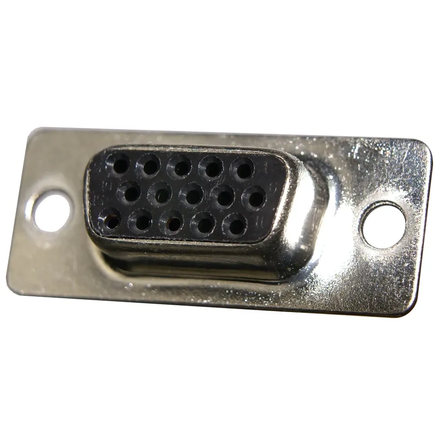
A D-sub 15 connector is a ubiquitous electrical interface characterized by its distinctive 'D' shaped metal shield, which encases 15 pins or sockets. This design provides mechanical stability and electromagnetic interference (EMI) protection. Primarily employed for the transmission of data and power, the D-sub 15 finds extensive applications across various electronic devices.
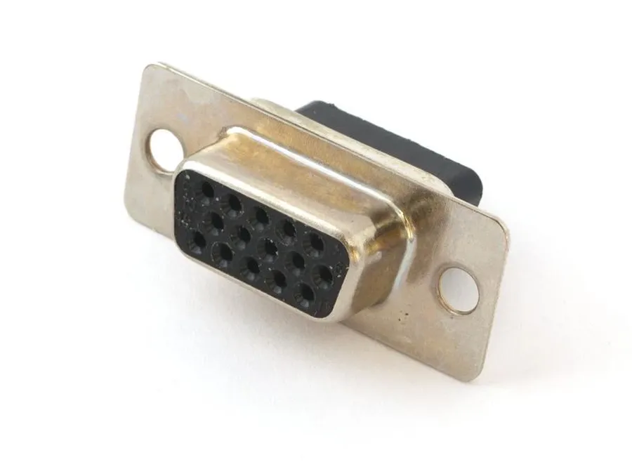
While the terms 'D-Sub 15', 'HD15', and 'DB15' are frequently used interchangeably, subtle but important distinctions exist. These differences primarily relate to the density and specific applications of the 15-pin D-sub connector, primarily seen in VGA connections. Understanding these nuances is crucial for proper connector identification and use.
| Term | Description | Typical Application |
|---|---|---|
| D-Sub 15 | General term for a D-shaped connector housing 15 pins or sockets. | Various applications including serial ports, video connections and legacy interfaces. |
| HD15 | High-Density 15-pin D-sub connector with a higher pin density, typically found in video graphics. | Primarily VGA (Video Graphics Array) ports for connecting monitors to computers. |
| DB15 | Another common term referring to a 15 pin version within the D-sub family, though less precise. | Used broadly, though often refers to D-Sub 15 interfaces. Can be confused with other D-sub connectors. |
The key distinction lies in density; HD15 connectors are high-density variants of the D-sub 15 standard, which means the pins are closer together compared to other D-sub connectors, however this distinction is not always consistent, where the term DB15 is used as a generic term for D-Sub connectors with 15 pins and can be used interchangeably depending on context. It's always best to check the specifications of the connector you are working with to avoid compatibility issues.
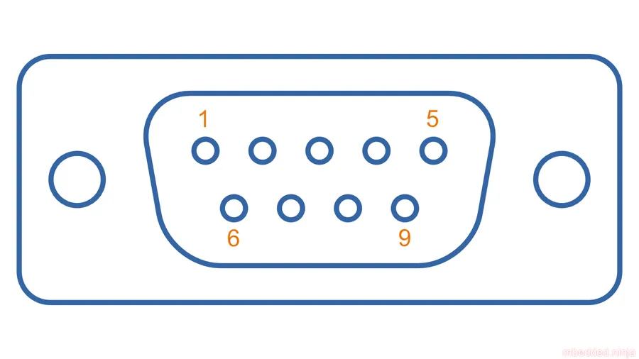
The D-Sub 15 connector's pinout specifies the function of each of its 15 pins, which is crucial for ensuring correct connections between devices and resolving connectivity problems. Precise knowledge of the pinout is vital when establishing connections between devices or performing any kind of troubleshooting.
| Pin Number | VGA Signal (Typical) | Other Common Signal | Description |
|---|---|---|---|
| 1 | Red Video | N/A | Carries the red color component of the video signal. |
| 2 | Green Video | N/A | Carries the green color component of the video signal. |
| 3 | Blue Video | N/A | Carries the blue color component of the video signal. |
| 4 | Monitor ID Bit 2 | DDC Data (SDA) | Used for identifying monitor type and capabilities; also carries the DDC data signal. |
| 5 | Ground | Ground | Provides a common ground reference for the signals. |
| 6 | Red Ground | N/A | Return path for the red video signal. |
| 7 | Green Ground | N/A | Return path for the green video signal. |
| 8 | Blue Ground | N/A | Return path for the blue video signal. |
| 9 | +5V DC | N/A | Provides power for EDID (Extended Display Identification Data) or other minor components. |
| 10 | Sync Ground | N/A | Return path for the synchronization signals. |
| 11 | Monitor ID Bit 0 | N/A | Used for identifying monitor type and capabilities. |
| 12 | DDC Data (SCL) | N/A | Carries the DDC clock signal. |
| 13 | Horizontal Sync | N/A | Carries the horizontal synchronization signal. |
| 14 | Vertical Sync | N/A | Carries the vertical synchronization signal. |
| 15 | Monitor ID Bit 1 | DDC Clock (SCL) | Used for identifying monitor type and capabilities. |
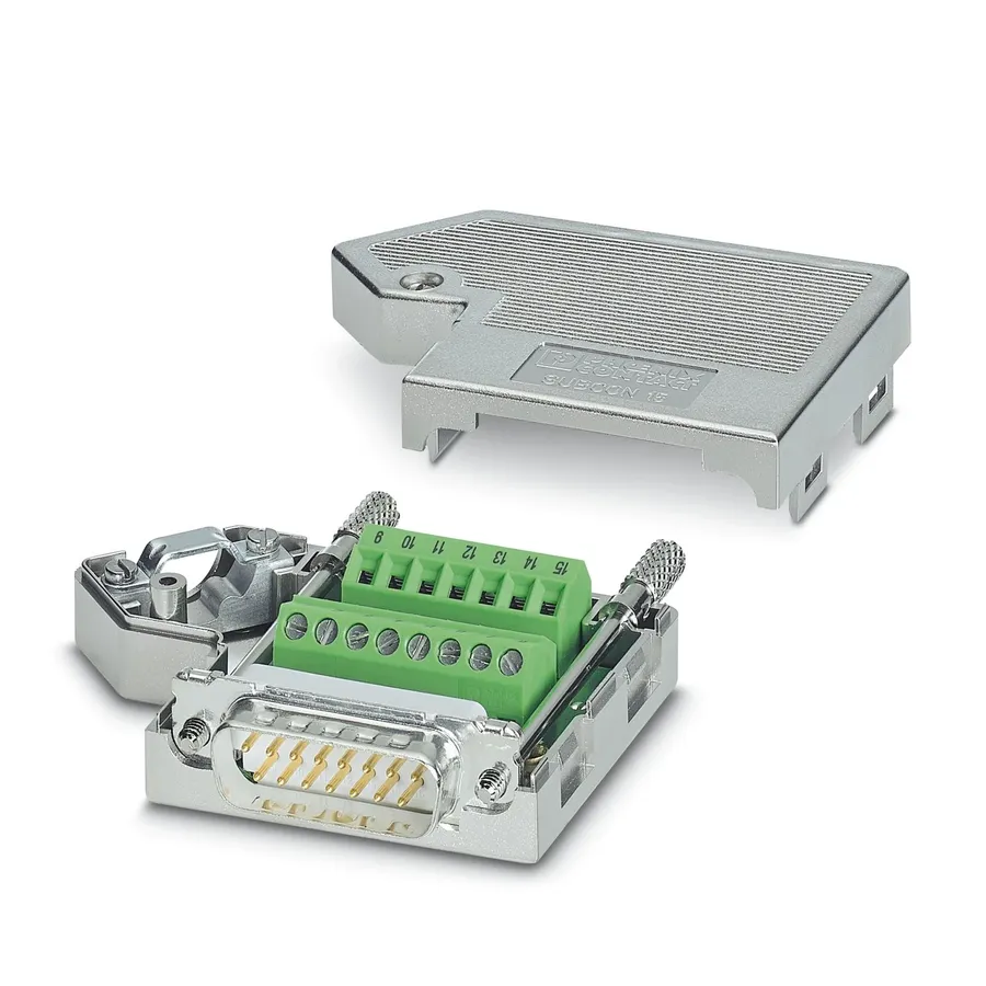
D-sub 15 connectors, characterized by their distinctive 'D' shaped metal shield and 15 pins, are versatile components found in various electronic applications. Their primary function is the transmission of data and power, making them integral to numerous devices. They are robust and relatively inexpensive, contributing to their widespread adoption in legacy and contemporary technologies.
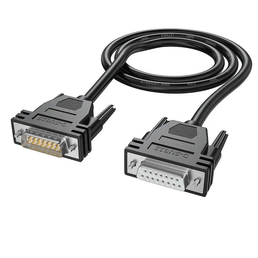
D-sub 15 connectors are designed with two distinct genders: male and female. The male connector features 15 protruding pins, while the female connector contains 15 corresponding sockets. These two types of connectors are designed to mate with each other, establishing an electrical connection that facilitates data and power transmission. Proper selection between male and female connectors is essential for seamless cable connections.
| Feature | Male D-Sub 15 | Female D-Sub 15 |
|---|---|---|
| Pin Structure | Protruding pins | Recessed sockets |
| Function | Typically found on cables and devices that are intended to output a signal. | Typically found on devices that are intended to receive a signal. |
| Visual Identification | Pins are visible. | Sockets are recessed. |
| Mating | Inserts into a female connector. | Receives a male connector. |
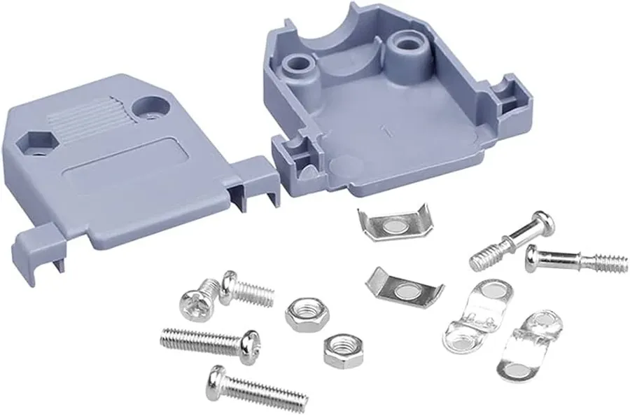
D-sub 15 connectors are not monolithic; they come in various termination styles tailored for different applications. These variations impact how the connector integrates into a system, affecting ease of assembly, durability, and suitability for specific use cases. Understanding these options is essential for proper connector selection.
| Connector Type | Description | Advantages | Disadvantages | Typical Applications |
|---|---|---|---|---|
| Solder Cup | Pins or sockets are terminated by soldering wires directly into cups. | Robust mechanical connection; suitable for direct wire attachment; provides strong electrical connection | Requires skilled soldering; not easily re-workable; can be time consuming | Prototypes; low volume custom cables; harsh environment applications; where mechanical strength is critical |
| PCB Mount (Right Angle/Vertical) | Pins designed to be directly soldered to a printed circuit board, typically right angle or vertical | Compact form; easy integration into PCB designs; scalable for mass production; optimized for automated assembly | Less flexible for direct wiring; requires specialized PCB design; difficult to rework | Internal PCB connections; mass production equipment; commercial electronics |
| Wire Wrap | Pins are designed for wire wrapping, where the wire is physically wrapped around the pin. | Very reliable gas-tight connection; ideal for prototyping; no soldering required; easy to modify | Time-consuming for mass production; not as compact; requires skilled user; can create stress on connector | Prototyping; low volume applications; where mechanical strength is critical |
| Crimp Contact | Pins are designed to mate with pre-crimped contacts, inserted into the connector housing. | Fast assembly; allows for modularity; can be easily replaced with tooling; consistent and reliable connections | Requires specialized crimping tools; components need more parts | Mass production of cable assemblies; applications requiring serviceability and replacements |
The longevity and reliability of a D-Sub 15 connector are significantly influenced by the materials used in its construction. These materials, from the contact plating to the insulator, determine the connector's ability to withstand environmental stresses and maintain consistent performance over its lifespan. Understanding the material science behind these components is crucial for selecting the right connector for a specific application, ultimately affecting the long-term cost and functionality.
| Component | Material Examples | Impact on Durability and Performance |
|---|---|---|
| Contact Plating | Gold, Tin, Nickel | Gold offers superior corrosion resistance and conductivity, ideal for high-reliability applications. Tin is cost-effective but prone to corrosion over time. Nickel is often used as a barrier layer. |
| Insulator Material | Thermoplastics (e.g., PBT, Nylon), Thermosets (e.g., Epoxy) | Thermoplastics offer good electrical insulation and are easy to mold but may degrade at high temperatures. Thermosets offer superior heat resistance, dimensional stability and chemical resistance. The insulator material prevents short circuits between the pins and housing. |
| Shell Material | Steel, Aluminum, Zinc Diecast | Steel provides excellent mechanical strength and shielding. Aluminum is lighter and provides good shielding. Zinc Diecast provides good shielding and is easy to machine. |
| Retention Mechanism | Spring Latches, Screw Locks | Spring latches offer quick engagement but less secure retention. Screw locks offer more secure retention, and are more resistant to vibrations and accidental disconnections. The mechanism ensures the connector remains mated under mechanical stress. |
The selection of materials should align with the intended application environment. For instance, connectors used in harsh environments may require gold plating and ruggedized shells for superior protection against corrosion, vibration, and extreme temperatures.
In summary, a thorough understanding of the material properties of D-Sub 15 connectors is essential for ensuring long-term reliability, performance, and cost-effectiveness. The initial investment in high-quality materials can greatly reduce long-term costs associated with connector failure.
This section addresses common questions regarding D-Sub 15 connectors, clarifying their function, relationship to VGA, and standardization.
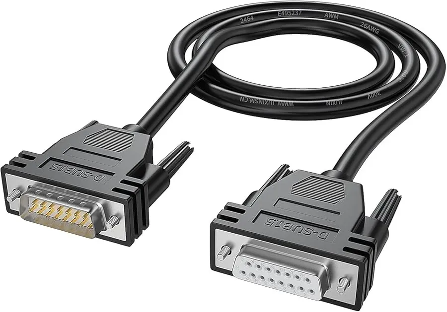
Choosing the correct D-Sub 15 connector and cable is crucial for ensuring reliable signal transmission and avoiding compatibility issues. The selection process should consider the specific application, signal type, environmental conditions, and mechanical requirements. A mismatch can lead to signal degradation, intermittent connections, or even damage to connected devices.
| Factor | Description | Considerations |
|---|---|---|
| Application | The specific use case of the D-Sub 15 connector. | VGA (video), serial, gameport, etc. |
| Signal Type | The type of signal being transmitted through the connector. | Analog, digital, or power |
| Pin Configuration | Ensures correct connections between the devices. | Standard VGA, custom pinouts |
| Shielding | The level of protection against electromagnetic interference (EMI). | Unshielded, partially shielded, fully shielded. |
| Cable Length | The physical length of the cable used to connect the devices. | Minimize length for signal integrity |
| Connector Gender | The male (pins) or female (sockets) configuration. | Ensure compatibility with mating connector. |
| Termination Method | How the cable is attached to the connector. | Solder cup, PCB mount, crimp |
| Environmental Conditions | The environment where the connector and cable will be used. | Temperature, humidity, chemicals, vibrations |
| Durability Requirements | The mechanical wear and tear to which the connector will be subjected | Frequent connections or rough handling |
| Regulatory Compliance | Any standards or certifications required for the application or geographical location. | RoHS, REACH, UL |
Effective troubleshooting of D-Sub 15 connections is crucial for maintaining seamless data transmission and device functionality. Many common issues, such as signal degradation, intermittent connectivity, and complete failure, can be resolved with a systematic approach, ensuring that devices dependent on this connector remain fully operational.
It is critical to ensure that the D-Sub 15 connection is properly secured and to verify cable integrity when troubleshooting. With a logical and methodical approach, many issues can be identified and resolved efficiently without the need for extensive technical expertise.
The D-sub 15 connector, despite its compact size, plays a vital role in various electronic applications. Understanding its specifications and applications can be helpful for anyone working with electronics. Its reliability makes it an essential component in both modern and legacy systems. By knowing the D-sub 15 connector's characteristics, you can ensure robust and efficient connectivity for your tech needs, now and in the future.

