In the world of electronics, the humble capacitor plays a vital role in storing electrical energy. You've likely encountered terms like 'uF' or 'mF' on these components, but what do they actually mean? This article delves into the world of mF capacitors, exploring their relationship with microfarads and providing a clear understanding of their use in various applications. Just as a dam regulates the flow of water, a capacitor regulates the flow of electricity, and understanding its markings like 'mF' is crucial for effective circuit design and maintenance.
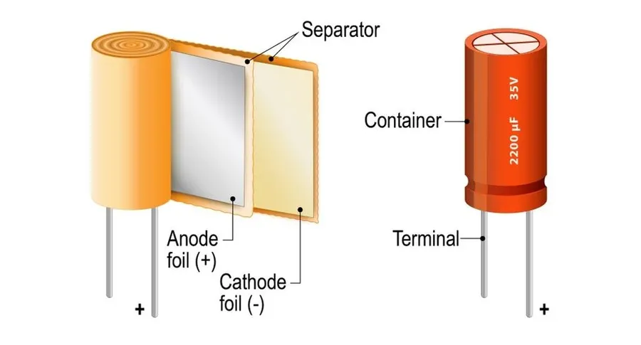
The notation 'mF' on a capacitor indicates its capacitance value, specifically in microfarads. A microfarad (mF) is a unit of electrical capacitance equal to one millionth of a farad (10⁻⁶ F). This unit is commonly used in electronics because the farad, the base unit of capacitance in the International System of Units (SI), is often too large for practical applications.
The terms 'mF' and 'uF' are indeed interchangeable; they both represent the unit microfarad, a measure of electrical capacitance. The symbol 'u' is the Greek letter 'mu' (µ), which is the standard abbreviation for 'micro'. Therefore, both 'mF' and 'µF' (or 'uF' as it commonly appears) indicate a capacitance value equal to one millionth of a farad (10^-6 F). This equivalence is fundamental in electronics and electrical engineering, where capacitors of this magnitude are frequently utilized.
| Term | Symbol | Value | Notes |
|---|---|---|---|
| Microfarad | mF, µF, uF | 10^-6 Farads | All denote the same value |
| Millifarad | mF | 10^-3 Farads | Rarely used for capacitor ratings |
| Farad | F | 1 Farad | A very large unit of capacitance |
The notation 'mF' on a capacitor is frequently a source of confusion, primarily due to its similarity to 'millifarad'. However, it unequivocally signifies 'microfarad', a unit representing one millionth of a farad (10⁻⁶ F), not one thousandth of a farad (10⁻³ F) which is a millifarad. The lowercase 'm' in 'mF' or the Greek letter 'μ' both denote 'micro' in this context. This distinction is critical for accurate interpretation of capacitor specifications and preventing potential errors in circuit design and component replacement.
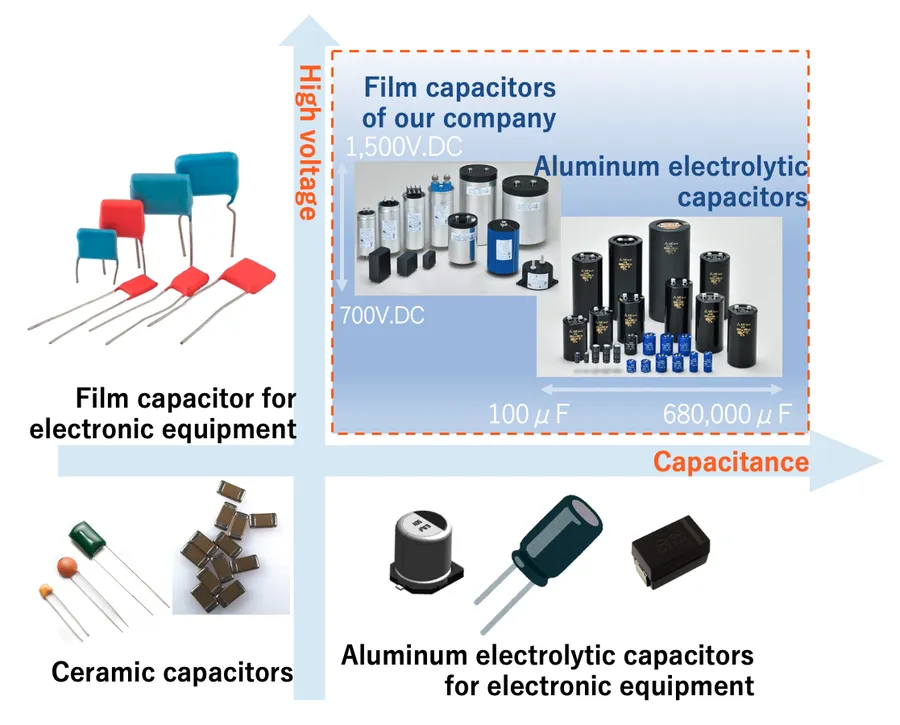
The farad (F) is the base unit of capacitance in the International System of Units (SI), but it represents an impractically large amount of capacitance for most electronic applications. Consequently, the microfarad (mF), which is one millionth of a farad (10^-6 F), is far more commonly used. This is because practical electronic circuits typically require capacitances in the range of microfarads, nanofarads, or even picofarads.
To illustrate the vast difference, consider that a 1-farad capacitor would be physically enormous and would be better suited for specialized high-energy storage applications. Conversely, the smaller sizes associated with microfarad, nanofarad, and picofarad capacitors allow for the design and construction of compact and efficient electronic circuits.
| Unit | Symbol | Value in Farads |
|---|---|---|
| Farad | F | 1 F |
| Millifarad | mF | 10^-3 F |
| Microfarad | µF or mF | 10^-6 F |
| Nanofarad | nF | 10^-9 F |
| Picofarad | pF | 10^-12 F |
Microfarad (mF) capacitors, also denoted as uF, are indispensable components across a wide spectrum of electronic applications due to their effective energy storage and release capabilities. Their versatility stems from their ability to operate efficiently within the capacitance ranges needed for diverse circuits.
| Application | Function | Capacitance Value Range |
|---|---|---|
| Power Supplies | Voltage Smoothing and Filtering | Typically 1mF to 1000s of mF, depending on the circuit requirements |
| Motor Starters | Provide starting torque | Typically 10mF to 100s of mF depending on the motor size |
| Audio Circuits | Signal Coupling and Filtering | Typically 0.1mF to 10s of mF, varies by frequency requirement |
| Filtering Circuits | Noise removal | Typically 0.001mF to 10s of mF |
| Timing Circuits | Timing pulses | Typically 0.01mF to 100s of mF depending on required time frame |
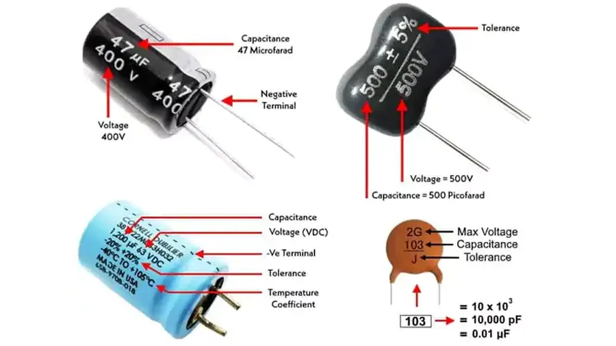
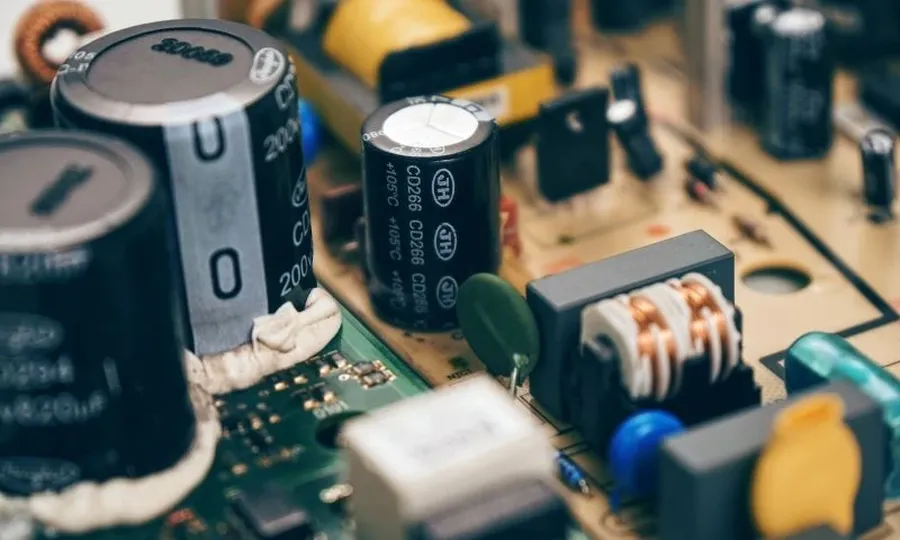
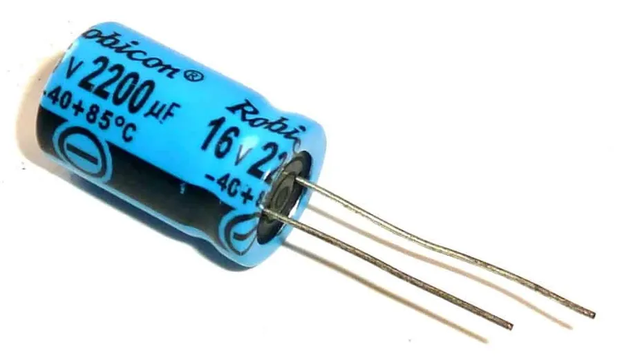
Capacitor markings provide crucial information for proper selection and application. These markings typically include the capacitance value, usually denoted in microfarads (mF or µF), and a voltage rating, indicating the maximum voltage the capacitor can withstand without failure. Understanding these markings is essential for safe and effective use of capacitors in electronic circuits.
| Marking Component | Description | Importance |
|---|---|---|
| Capacitance Value | Indicated in mF, µF, or sometimes a lowercase 'm' or the Greek letter 'mu' followed by 'F'. Specifies the capacitor's ability to store electrical charge. | Crucial for proper circuit functionality. Incorrect capacitance can lead to circuit malfunction. |
| Voltage Rating | Indicates the maximum voltage that the capacitor can safely handle. Expressed in volts (V). | Vital to prevent capacitor failure. Operating beyond the rated voltage can cause permanent damage or catastrophic failure. |
| Tolerance | The allowable deviation from the stated capacitance value. Often expressed as a percentage (e.g., ±10%). | Important for precision applications where the actual capacitance needs to be within a specific range. |
| Temperature Rating | Indicates the temperature range within which the capacitor can operate safely and effectively. Expressed in degrees Celsius (°C). | Important to ensure long lasting performance and reduce failure in different operating temperatures. |
| Polarity Indicator | On polarized capacitors, indicates which terminal should be connected to the positive and negative sides of the circuit. | Essential to observe proper polarity on polarized capacitors as an incorrect connection may result in failure. |
When replacing an mF capacitor, several critical factors must be considered to ensure proper circuit function and safety. The most important considerations are the capacitance value, voltage rating, and polarity.
Replacing a capacitor without proper consideration of these parameters can result in functional issues, reduced lifespan, or even catastrophic failure. Here's a detailed look at each consideration:
| Parameter | Requirement | Consequence of Incorrect Value |
|---|---|---|
| Capacitance | Match original mF value | Circuit malfunction, damage |
| Voltage Rating | Equal to or greater than original | Premature failure, potential fire |
| Polarity | Match the original | Capacitor damage, circuit failure |
This section addresses common questions about mF capacitors, clarifying their meaning, usage, and relationship to other capacitance units. We aim to provide precise and authoritative answers to these frequently asked questions.
In conclusion, the 'mF' marking on a capacitor signifies microfarads, a crucial unit for expressing capacitance. Understanding that 'mF' and 'uF' are the same helps in correctly identifying and replacing capacitors. From powering home appliances to complex electronic systems, mf capacitors, and those marked with the equivalent 'uF', serve as indispensable components in electrical circuits, ensuring the reliable flow and storage of electrical energy. As technology evolves, the importance of understanding these fundamental concepts remains essential for anyone involved in electronics.

