Understanding Resistors Connected in Series: A Comprehensive Guide
2025.02.07
Imagine a string of holiday lights; each bulb connected one after another. This simple setup mirrors how resistors are connected in series within electronic circuits. Just as a single broken bulb can disrupt the entire light string, understanding how resistors connected in series affect current flow and resistance is crucial in electronics. This article delves into the fundamentals of series resistor circuits, their characteristics, and practical applications.
What are Resistors Connected in Series?
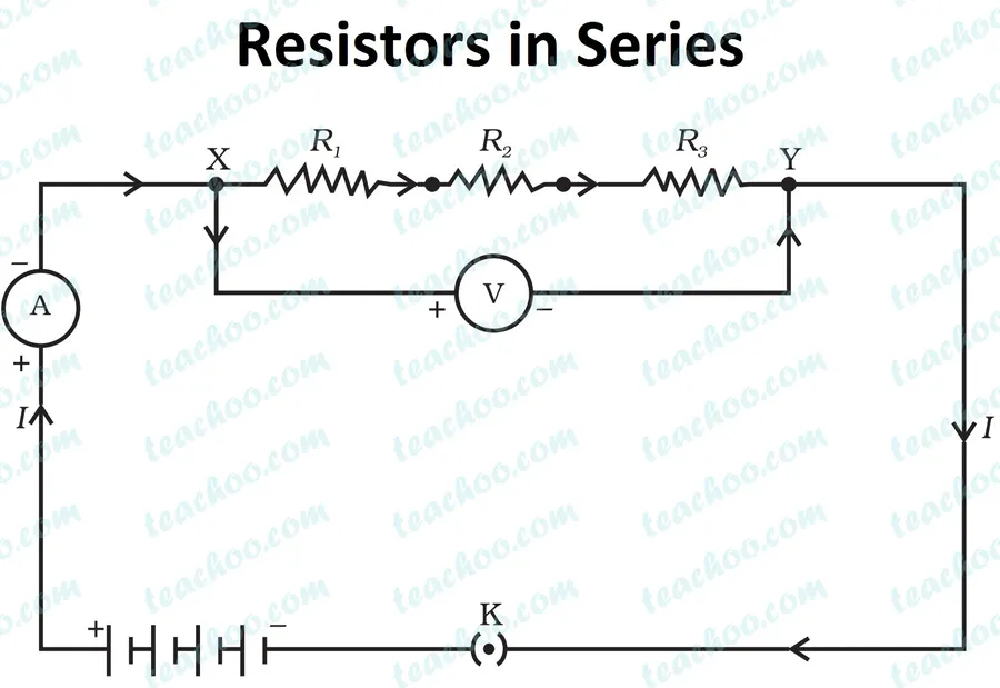
Series Resistor Circuit Diagram
Resistors in a series connection are characterized by their sequential arrangement along a single conductive path. This configuration mandates that the identical electrical current traverses each resistor in the series, establishing a singular route for electron flow. The series connection is fundamental to electrical circuit design and analysis, affecting current, voltage, and overall resistance within the circuit.
Current in a Series Circuit
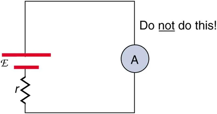
Ammeter in Series Circuit
A fundamental characteristic of a series circuit is the uniformity of current flow throughout the circuit. This means that the electrical current, measured in amperes (A), is identical at every point along the single path, irrespective of the resistance value of each component.
This principle is rooted in the conservation of charge. Since there is only one path for the current to take, all the charge carriers (electrons in most cases) must flow through each resistor, thus the current must be the same in each element of the series.
Calculating Total Resistance in a Series Circuit
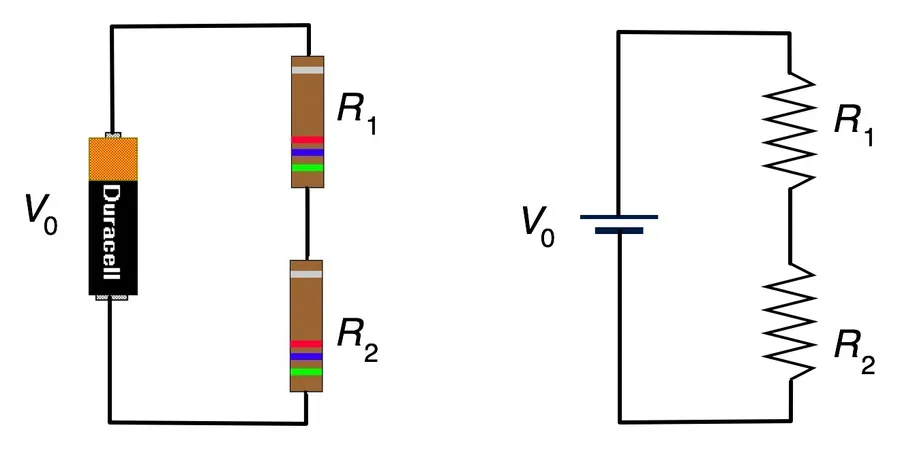
Calculating Series Resistance
In a series circuit, the total resistance is determined by the simple addition of the individual resistances. This fundamental principle dictates that the overall opposition to current flow increases with each additional resistor in the series, leading to predictable circuit behavior.
The mathematical representation of total resistance (R_total) in a series circuit with 'n' number of resistors is given by the following formula:
R_{total} = R_1 + R_2 + R_3 + ... + R_n
Where:
- R_total is the total resistance of the series circuit.
- R_1, R_2, R_3, ..., R_n are the individual resistances of each resistor in the series.
This formula underscores a crucial point: every added resistor, regardless of its value, contributes to an increased total resistance in the circuit. The increase in overall resistance is directly proportional to the value of the added resistor. It also indicates that the total resistance is always greater than the largest single resistance in the series.
Resistor Count
Individual Resistance (Ohms)
Total Resistance (Ohms)
2
R1=10, R2=20
R_total = 10 + 20 = 30
3
R1=10, R2=20, R3=30
R_total = 10 + 20 + 30 = 60
4
R1=10, R2=20, R3=30, R4=40
R_total = 10 + 20 + 30 + 40 = 100
Voltage Distribution in a Series Circuit
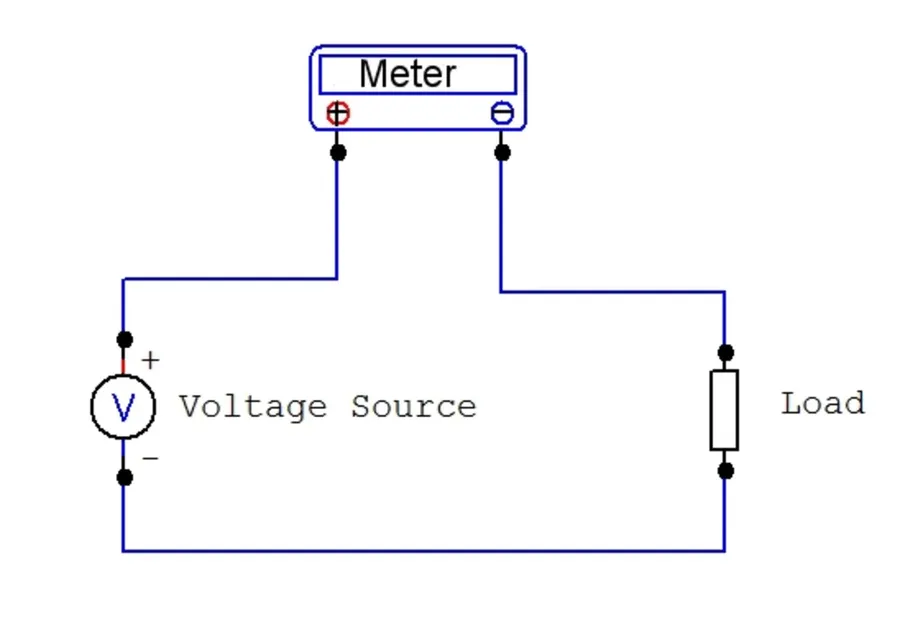
Voltmeter in Series Circuit
In a series circuit, the total applied voltage is not uniformly distributed across all resistors but rather divided among them, a phenomenon known as voltage division. This distribution is directly proportional to the resistance of each component; resistors with larger resistances will exhibit greater voltage drops compared to those with smaller resistances.
Understanding voltage distribution in series circuits is crucial for designing and analyzing electronic circuits. The voltage drop across each resistor can be calculated using the voltage divider rule, derived from Ohm's Law and Kirchhoff's Voltage Law, as follows:
V_i = V_{total} * (R_i / R_{total})
Where:
- Vᵢ is the voltage drop across resistor Rᵢ.
- Vtotal is the total applied voltage across the series circuit.
- Rᵢ is the resistance of the specific resistor you are analyzing.
- Rtotal is the total equivalent resistance of the series circuit.
Parameter
Description
Voltage Drop (Vᵢ)
The voltage measured across an individual resistor in a series connection.
Total Voltage (Vtotal)
The overall voltage applied to the entire series circuit.
Individual Resistance (Rᵢ)
The value of a specific resistor within the series connection.
Total Resistance (Rtotal)
The sum of all resistances in a series circuit.
This relationship highlights that resistors with larger values will experience a larger voltage drop. This principle is fundamental in many electronic applications, from voltage dividers to biasing transistors.
Resistors in Series Examples and Applications
Series Resistors Application
Resistors connected in series are fundamental building blocks in electronics, providing essential functionality across a wide spectrum of applications. Their primary roles involve voltage division, current limiting, and the creation of specific resistance values, underpinning countless electronic circuits.
Voltage Dividers Series resistors form the basis of voltage dividers, circuits used to reduce a voltage to a specific fraction. This is crucial in situations where a lower voltage is needed for a particular component, such as biasing transistors, operational amplifiers, or microcontrollers. The voltage drop across each resistor is proportional to its resistance value, allowing for precise voltage control.
Current Limiting Resistors in series are used to limit the current in a circuit, protecting sensitive components from overcurrent damage. For instance, connecting a series resistor with a light emitting diode (LED) protects it from damage due to excessive current. The Ohm's law governs this relationship, specifying how resistance influences current flow for a given voltage.
Creating Custom Resistance Values When a specific resistor value is not available, combining standard resistors in series allows for creation of the desired resistance value. This method is commonly employed in prototyping and circuit design where non-standard resistance values might be necessary. By carefully selecting resistor values, the equivalent total resistance in the series can be calculated precisely using the sum of individual resistances.
Basic Electronic Circuits Many fundamental electronic circuits rely on series resistors, forming the backbone of basic circuit design. These can range from simple LED circuits to more complex circuits that use operational amplifiers. The predictability of current and voltage behavior in series configurations makes them easy to analyze and design with.
Lighting Circuits Series resistors are also used in lighting applications. In some lighting circuits, LEDs are connected in series to achieve a particular level of brightness and ensure each LED gets its designed operational current and voltage. This configuration helps in controlling the overall circuit behavior and avoiding failures from over driving the lighting elements.
Practical Tips for Working with Series Resistors
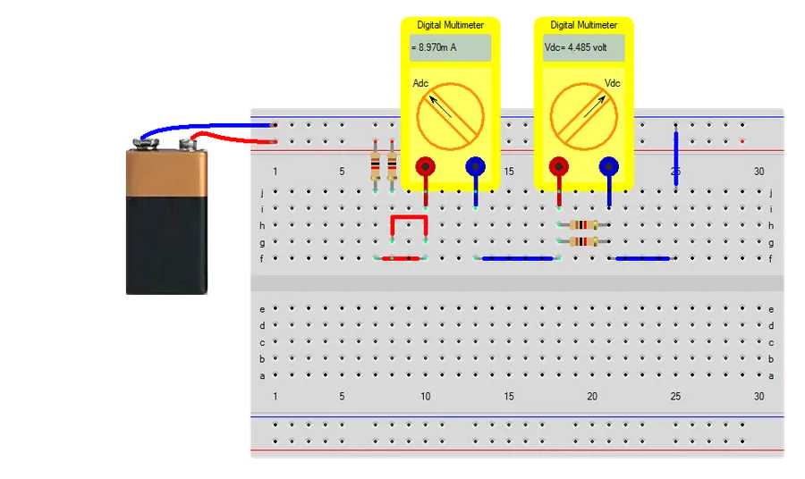
Series Resistors on Breadboard
Successfully implementing series resistor circuits requires careful attention to several key practical considerations, ensuring both functionality and safety. These tips encompass aspects from component selection to circuit construction and operation.
Accurate Resistor Values Always use resistors with the correct resistance value as specified by the design. Verify the color bands or use a multimeter to measure the resistance before including them in the circuit. Incorrect values will lead to unpredictable behavior in the circuit.
Power Ratings Each resistor has a maximum power rating (measured in watts) that it can safely dissipate. Ensure that the power dissipated by each resistor in the series circuit is below this rating to prevent overheating and component failure. The power dissipated can be calculated by P = I²R, where I is the current through the resistor and R is the resistance. Choose a resistor with a power rating that provides an ample safety margin. A common rule of thumb is to use resistors with at least twice the power rating required for the application.
Current Considerations Understand that current is the same throughout a series circuit. The current is defined by I=V/R_total where V is the applied voltage and R_total is the sum of all the resistors. Accurately predicting the amount of current is vital for choosing the right power ratings for resistors. Furthermore, if the current exceeds the rated values for the resistors or power supply, the circuit can malfunction or even cause irreversible damage to the components.
Secure Connections When building a physical circuit, make sure the connections between the resistors are strong and have minimal resistance. Proper soldering is necessary for permanent circuits while breadboards can be used for prototyping. Avoid loose connections, as they can cause intermittent operation or excessive heat due to unwanted resistance.
Heat Dissipation Consider the heat generated by the resistors. If the resistors are dissipating a significant amount of power, they may need adequate cooling measures such as heat sinks or spacing to allow airflow. Adequate heat dissipation prevents overheating which can cause premature component failure. This is more relevant when working with high power systems.
Careful Calculations Accurate calculation is essential in circuit design. Double check all calculations before assembling the circuit to avoid mistakes. Specifically, make sure the total resistance and the resultant current of the circuit are properly calculated. Use tools like a calculator or circuit simulation software to aid in this process. Understanding the relationships between voltage, current, and resistance is a MUST for designing proper circuits
Frequently Asked Questions About Resistors in Series Circuits
Understanding series resistor circuits can be challenging, so we've compiled a list of frequently asked questions to help clarify common points of confusion and practical considerations.
What happens when a resistor fails (opens) in a series circuit? If a resistor fails in a series circuit by becoming an open circuit, the current flow through the entire circuit ceases. This is because a series circuit only provides a single path for current, and an open at any point will break the circuit.
What is the fundamental difference between series and parallel resistor circuits? In a series circuit, resistors are connected sequentially, end-to-end, forming a single path for current. In contrast, parallel circuits offer multiple paths for current to flow, with resistors connected side-by-side.
How does adding more resistors in series affect the total resistance? Adding more resistors in series *always* increases the total resistance of the circuit. The total resistance is the simple sum of all the individual resistances (R_total = R1 + R2 + R3 + ... + Rn).
How is the voltage distributed across resistors in a series circuit? The voltage applied across a series circuit is divided among the resistors. The voltage drop across each resistor is directly proportional to its resistance; larger resistances will experience a greater voltage drop. This is known as voltage division.
Can I use resistors of different values in a series circuit, and how does it affect the current flow? Yes, resistors of different values can be used in series. The same current flows through *all* resistors in the circuit regardless of their resistance value. However, voltage drop across each resistor will vary depending on its individual resistance, as stated by Ohm's Law (V=IR).
What happens to power dissipation in a series circuit when you add more resistors? Adding more resistors in series increases the total resistance and usually reduces the overall current (given the same voltage source). However, the power dissipated by each resistor depends on its individual resistance and the current flowing through it (P=I^2*R), and must be considered when selecting the appropriate rated components.
How do I identify if resistors are connected in series in a circuit diagram? In a circuit diagram, series resistors are connected one after the other along a single line, without branching paths for the current to take.
Series Resistors vs. Parallel Resistors: Key Differences
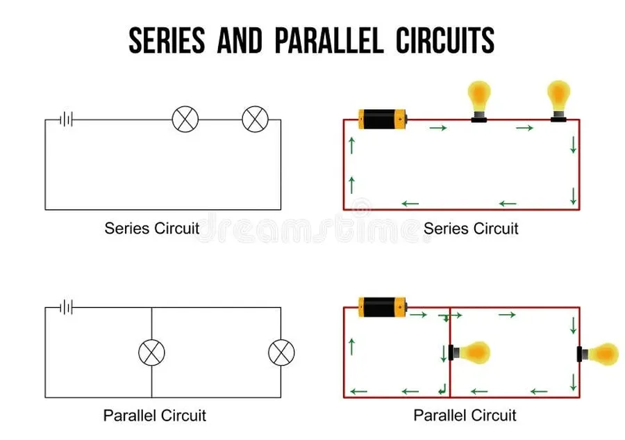
Series vs Parallel Circuit
Understanding the fundamental differences between series and parallel resistor configurations is crucial for circuit design and analysis. While series resistors are arranged sequentially along a single path, parallel resistors are placed side-by-side, offering multiple paths for current flow. These contrasting configurations lead to distinctly different circuit behaviors, particularly concerning total resistance and current distribution.
Characteristic
Series Resistors
Parallel Resistors
Current Flow
Single path; same current through all resistors
Multiple paths; current divides among branches
Total Resistance
Increases as more resistors are added; R_total = R1 + R2 + ... + Rn
Decreases as more resistors are added; 1/R_total = 1/R1 + 1/R2 + ... + 1/Rn
Voltage Drop
Voltage is divided across resistors; drop proportional to resistance
Voltage is the same across all resistors
Circuit Behavior
Failure of one resistor breaks the entire circuit
Failure of one resistor may not affect the other parallel branches
Troubleshooting Series Resistor Circuits
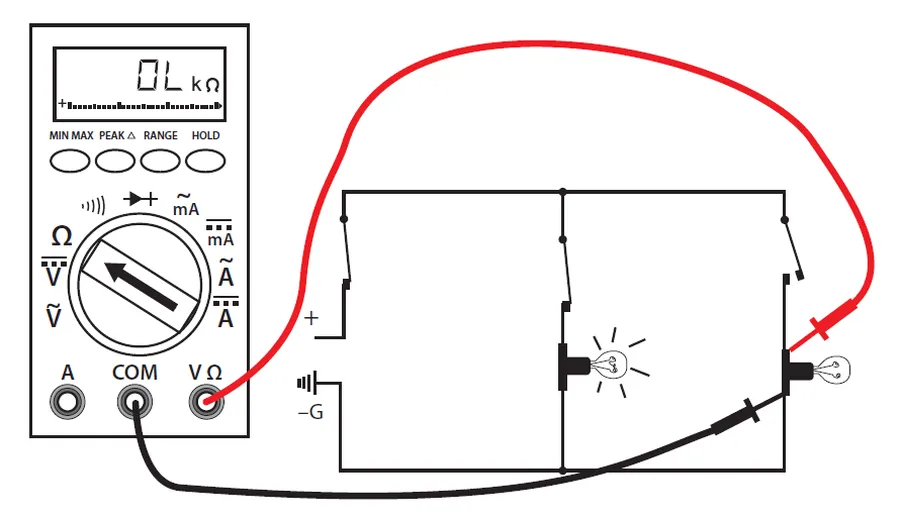
Multimeter Measuring Resistance
Troubleshooting series resistor circuits involves systematic checks to identify and rectify issues that prevent the circuit from functioning as intended. Common problems include open circuits, incorrect resistor values, and connection faults. Efficient troubleshooting requires a clear understanding of series circuit behavior and the use of appropriate diagnostic tools.
Open Circuits An open circuit occurs when there's a break in the conductive path, preventing current flow. This can be caused by a broken component, a faulty connection, or a break in the wire. Use a multimeter to check for continuity across all points in the circuit. A break will show as a very high resistance (often infinite) on the multimeter.
Incorrect Resistor Values Ensure that the resistors used match the specified values. Mismatched resistors can lead to incorrect voltage distribution and circuit malfunction. Always verify resistor values using their color codes or a multimeter. It is crucial to confirm that the resistor's actual value is within tolerance of its nominal value as printed on the component or specified in the design.
Connection Faults Poor solder joints, loose wires, or corroded connections can cause high resistance or intermittent failures. Carefully inspect all connections and ensure they are mechanically robust and electrically sound. Bad connections can also cause heat generation and failure of the component. If using a breadboard, verify the connections as well since they can become loose over time.
Component Failure Resistors can fail due to overheating, overcurrent, or age. If a component is suspected to be faulty, replacing it can help isolate if the component is the cause of the problem. A visual inspection for burn marks, cracks, or signs of overheating is essential. If a component is found to be bad, the design should be analyzed to see if improvements can be made to the circuit so that it does not happen again.
Power Supply Issues Verify that the power supply is delivering the correct voltage and current needed for the circuit. Measure the voltage at the terminals where the circuit is powered and test the power supply directly. Insufficient power or incorrect voltage can lead to erratic behavior or complete circuit failure.
Multimeter Testing A multimeter is an essential tool. Measure voltage drops across individual resistors to verify voltage division and check for continuity to identify open circuits. Use the Ohm setting on the multimeter to measure resistor values and check for high resistance in any connection points. Record your readings while troubleshooting and carefully analyze what these readings tell you about the state of the circuit.
Understanding how resistors connected in series behave is fundamental to grasp basic electrical engineering. Resistors connected in series are not just about adding up the resistance. They're about understanding how the current flows, how voltage is divided, and how the entire circuit behaves when individual components are interconnected. This article provided an in-depth look at series resistor circuits, their applications, and common troubleshooting tips, equipping you to confidently work with and design simple electrical circuits.