The ubiquitous 100k potentiometer, a seemingly simple component, plays a vital role in countless electronic devices, from audio volume controls to precise sensor adjustments. Just as a dimmer switch allows you to fine-tune light intensity, a 100k potentiometer provides a variable resistance, granting you precise control over circuits. This article delves into the intricacies of 100k potentiometers, exploring their types, applications, and practical considerations, bridging the gap between theoretical knowledge and real-world usage.
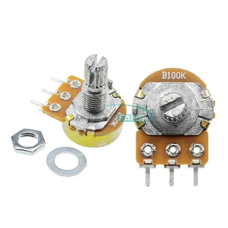
A 100k potentiometer, fundamentally a variable resistor, provides adjustable resistance up to 100,000 ohms (100 kΩ). This adjustability, achieved through a rotating knob or sliding mechanism, is vital for dynamic control within electronic circuits, where precise voltage division is required. The component's construction features three terminals: two connect to the opposing ends of the resistive track, while the third, the wiper, facilitates variable output.
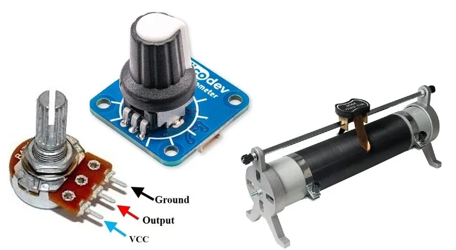
100k potentiometers are not monolithic; they manifest in diverse physical forms, each tailored to specific applications. The core functionality of a 100k potentiometer—to provide a variable resistance up to 100,000 ohms—is constant, but the user interface and adjustment mechanisms vary significantly.
| Type | Description | Typical Applications | Adjustment Method | User Accessibility |
|---|---|---|---|---|
| Rotary | Features a rotating shaft or knob to vary the resistance. This is the most common type of potentiometer. | Volume controls, general-purpose adjustment, user interface knobs. | Rotation of knob/shaft | High |
| Slide | Uses a linear slider to adjust the resistance. Provides a visual indication of the setting. | Audio mixing consoles, equalizers, lighting control boards. | Linear sliding motion | High |
| Trimpot (Trimmer Potentiometer) | Small, typically board-mounted potentiometers designed for fine tuning and calibration. Not intended for frequent user adjustments. | Calibration of circuits, sensor adjustments, internal settings. | Screwdriver or small tool adjustment | Low |
The selection of potentiometer type should be based on the design constraints and user interaction needs of the final product. Each type brings its own advantages and disadvantages, which must be carefully considered.
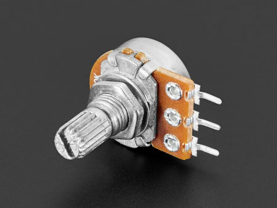
The selection of a potentiometer's taper, specifically linear or logarithmic (audio), is pivotal to its performance within a circuit. A 100k potentiometer's taper determines how the resistance changes as the adjustment mechanism is manipulated. These two main types serve distinct purposes in applications, based on their specific resistive characteristics.
| Feature | Linear Taper | Logarithmic (Audio) Taper |
|---|---|---|
| Resistance Change | Uniform change across the adjustment range. | Non-uniform change, typically with a larger change at one end of the range. |
| Application | Ideal for fine-tuning and control systems, where a linear response is required. | Optimized for audio volume control and human perception of loudness. |
| Typical Use Cases | Light dimmers, motor speed controllers, general calibration | Volume control in audio amplifiers, mixing consoles, and audio equipment. |
| Human Perception | Resistive change is directly proportional to the adjustment. | Resistive change mimics human perception of audio with smaller changes at low volumes and larger changes at higher volumes. |
Choosing between linear and logarithmic tapers depends on the specific requirements of your project. Understanding the difference is critical to achieving the desired functionality. For instance, for linear adjustments in a circuit or sensor calibration, linear taper is more suitable, while for audio controls, logarithmic taper aligns with the way the human ear perceives sound.
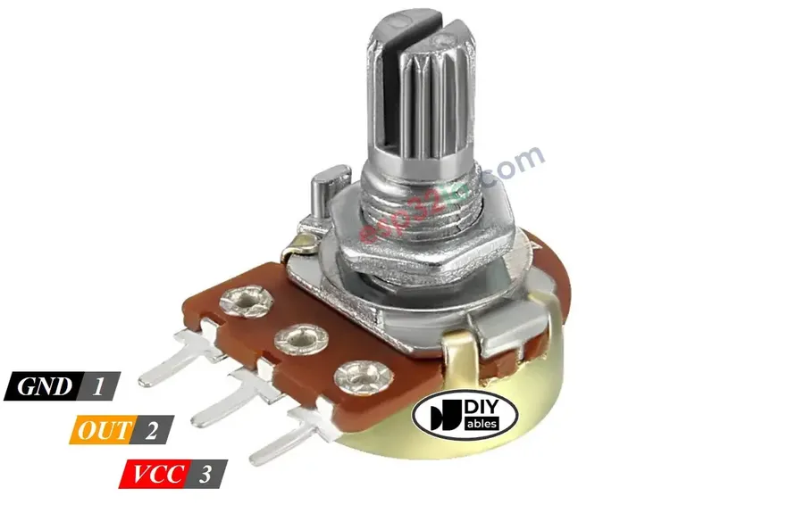
Correctly understanding the pinout and wiring of a 100k potentiometer is fundamental for its proper integration into any electronic circuit. The potentiometer features three terminals: two outer pins connected to the ends of the resistive track and a center pin connected to the wiper. Applying voltage across the outer pins creates a voltage divider, with the center pin's voltage adjustable by the potentiometer's knob or slider. Improper wiring can lead to component damage, inaccurate readings, or circuit malfunction.
| Pin | Description | Function |
|---|---|---|
| Pin 1 | One end of the resistive track | Typically connected to the voltage source (VCC) or ground. |
| Pin 2 (Center) | Wiper or variable output | Provides the adjustable voltage output, which varies as the potentiometer is adjusted |
| Pin 3 | The other end of the resistive track | Typically connected to ground or the other side of the voltage source. |
The pinout is universally consistent across most 100k potentiometers, but it's prudent to consult the datasheet, especially for less common variants. Incorrect wiring, such as connecting the voltage source directly to the wiper, can lead to damage by creating a short circuit. Always ensure the voltage source connects to the outer pins, and the adjustable output is taken from the wiper.
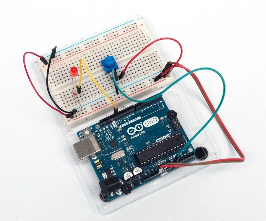
The 100k potentiometer is a highly adaptable component, finding use across a wide spectrum of electronic devices due to its ability to provide variable resistance. This capability allows for precise control and fine-tuning of electronic parameters, making it indispensable in various applications. The following explores some common uses.
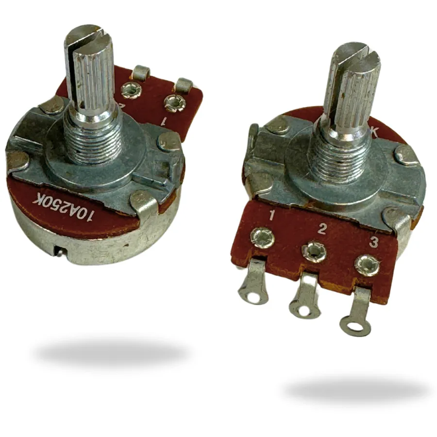
Selecting the appropriate 100k potentiometer requires a careful evaluation of your project's specific needs. This involves considering several factors, such as the potentiometer's physical attributes, electrical characteristics, and the application's environmental conditions. Ensuring that you choose the right component will directly impact the performance and longevity of your device.
| Factor | Considerations |
|---|---|
| Physical Size | Determine the space available within your project for mounting the potentiometer. Consider both the diameter of the base and the length of the shaft. |
| Mounting Type | Choose between panel mount (secured with a nut and washer), breadboard-friendly (with pins that plug into a breadboard), or PCB mount (soldered onto a circuit board) based on your assembly needs. |
| Taper | Select between a linear taper (consistent resistance change) for general adjustment, and a logarithmic or audio taper (non-linear change suited to audio) based on the needs of the application. Linear is often denoted with a 'B' suffix, and logarithmic as 'A' or 'C'. |
| Power Rating | Ensure that the potentiometer's power rating (in Watts) exceeds the maximum power it will experience within your circuit to prevent damage or premature failure. |
| Environmental Factors | Consider the operating temperature range and humidity conditions. Some potentiometers are more robust and resistant to environmental degradation. |
| Shaft Type | Select the appropriate shaft type. D-shafts prevent slippage when using a knob with a corresponding D-shaped hole. Flatted, knurled, or smooth shafts can also be selected based on your desired knob. |
| Switching | If you need an on/off switch in addition to the potentiometer, ensure it has that built-in feature, often a push/pull or rotate switch. |
| Accuracy and Tolerance | Consider the tolerance rating if precise resistance is required, as well as the resolution of the resistance change, especially with multi-turn potentiometers. |
| Resistance Range | While the maximum resistance is 100kΩ, the precision and range needed within this may be a specific requirement. |
The primary distinction between a 10k potentiometer and a 100k potentiometer lies in their maximum resistance values. A 10k potentiometer offers a maximum resistance of 10,000 ohms, while a 100k potentiometer reaches 100,000 ohms. This tenfold difference in resistance range is the key factor in determining which component is more suitable for a particular application.
| Feature | 10k Potentiometer | 100k Potentiometer |
|---|---|---|
| Maximum Resistance | 10,000 ohms (10kΩ) | 100,000 ohms (100kΩ) |
| Current Handling | Higher current for same voltage | Lower current for same voltage |
| Typical Applications | Lower impedance circuits, current sensing, adjustments in higher current circuits | Higher impedance circuits, audio volume control, adjustments in low current circuits |
| Noise Sensitivity | Less susceptible to noise | More susceptible to noise due to higher resistance |
The choice between a 10k and 100k potentiometer depends on the specific impedance requirements of the circuit. The 10k potentiometer is better suited for circuits where lower resistance is needed and higher current will flow, whereas the 100k potentiometer is more suitable for circuits requiring higher resistance and where lower current is desired. Understanding this distinction is crucial for effective circuit design and operation.
This section addresses common questions regarding 100k potentiometers, providing clear and concise answers to help users make informed decisions about their applications.
In conclusion, the 100k potentiometer is a highly versatile electronic component, providing variable resistance essential for many control applications. From adjusting audio volume to fine-tuning sensor circuits, understanding its different types, tapers, and pinouts is key to successful integration into electronic projects. By selecting the right 100k potentiometer, whether a linear or logarithmic taper, your design will meet your specific requirements. The 100k potentiometer, though small, is a cornerstone in the landscape of electronics.

