Understanding the 100uF Capacitor: Uses, Types, and Selection Guide
2025.02.06
In our daily lives, from smartphones to large industrial machines, the unsung hero of many electronic circuits is the humble capacitor. Among them, the 100uF capacitor stands out for its versatile usage. This article will dissect the 100uF capacitor, exploring its function, types (like the ubiquitous 100uF electrolytic capacitor), selection considerations, and its crucial role in modern electronics, bringing together the wonders of technology and how they impact our daily experiences. We'll go through everything from basics to advanced applications.
What is a 100uF Capacitor?
100uF Capacitor
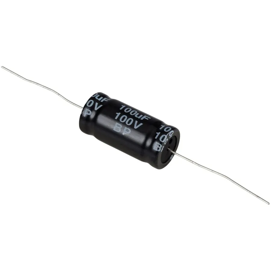
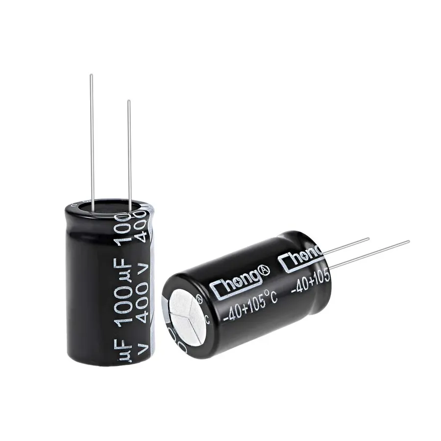
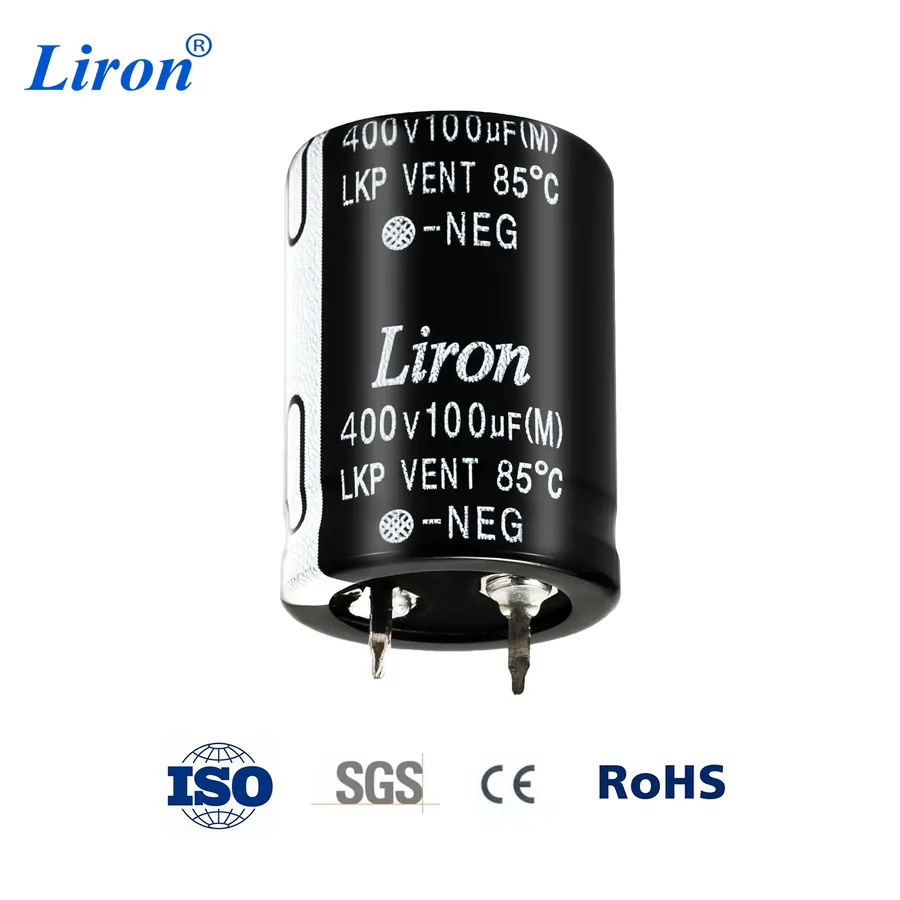
A 100uF capacitor is a fundamental passive electronic component characterized by its ability to store electrical energy within an electric field. The designation '100uF' signifies its capacitance, a measure of its charge-storing capacity, which is specifically 100 microfarads. This component is ubiquitously employed across numerous electronic circuits, fulfilling a diverse range of functions.
Different Types of 100uF Capacitors
Different Types of 100uF Capacitors
While the term '100uF capacitor' often evokes the image of an electrolytic capacitor, it's crucial to recognize that several other types exist, each with unique characteristics. These variations allow for optimized performance across a broad range of applications. Understanding the distinctions between ceramic, film, tantalum, and electrolytic 100uF capacitors is paramount for effective circuit design and component selection.
Capacitor Type
Key Characteristics
Typical Applications
Advantages
Disadvantages
Electrolytic
Polarized, high capacitance, moderate cost, larger size
Power supply filtering, decoupling, audio coupling
High capacitance in small volume
Polarized, limited life, higher ESR
Ceramic
Non-polarized, low ESR, good high-frequency response, temperature dependent capacitance
Bypass capacitors, high-frequency filtering
Low cost, small size, good high-frequency performance
Capacitance varies with voltage and temperature
Film
Non-polarized, good temperature stability, good tolerance
Precision timing circuits, audio applications
Good temperature stability, low ESR
Larger size, higher cost
Tantalum
Polarized, small size, good stability, lower ESR than electrolytic, sensitive to overvoltage and reverse voltage
SMD applications, compact devices, filtering in critical applications
High volumetric efficiency, low ESR
Expensive, polarized, can fail catastrophically
Electrolytic 100uF Capacitor: Characteristics and Applications
Electrolytic 100uF Capacitor
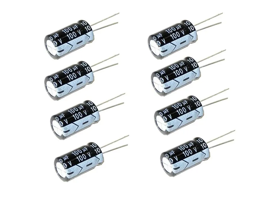
Electrolytic 100uF capacitors are a prevalent type of capacitor characterized by their relatively high capacitance value and polarized nature, commonly found in radial and Surface Mount Device (SMD) configurations. Their construction employs a liquid or gel electrolyte, enabling high capacitance but also introducing unique properties that are crucial for circuit design.
Characteristic
Description
Polarization
Electrolytic capacitors are polarized, requiring correct terminal orientation during installation. Incorrect polarity can lead to damage and failure.
Construction
Utilizes a liquid or gel electrolyte which allows for a high capacitance in a relatively small package.
Configurations
Available in through-hole (radial) and surface-mount (SMD) versions.
Voltage Ratings
Standard voltage ratings are available: 16V, 25V, 35V, and 100V. Other voltage ratings are also available.
Typical Applications
Used for power supply filtering, signal decoupling, and smoothing.
The selection of an electrolytic capacitor is largely determined by application requirements, considering parameters such as voltage rating, temperature stability, and expected lifespan. They offer an economic and compact solution for capacitance in a wide range of applications.
Polarity and Installation of Electrolytic 100uF Capacitors
Electrolytic 100uF Capacitor on PCB
Electrolytic 100uF capacitors are polarized components, characterized by designated positive and negative terminals. This polarity is a crucial aspect to consider during installation, as incorrect placement can lead to capacitor failure and damage to the surrounding circuit. This section details the identification of polarity markings and provides best practices for ensuring correct installation.
Polarity Markings Electrolytic capacitors are typically marked with a stripe or a series of minus signs on the casing adjacent to the negative terminal. The positive terminal is generally the longer lead or may have no marking.
Radial vs SMD Radial capacitors feature leads extending from the bottom of the component, while SMD (Surface Mount Device) capacitors feature contacts on the bottom of the component. SMD electrolytic capacitors will have a marking on the case to denote the negative side.
Importance of Correct Installation Incorrect polarity can result in overheating, electrolyte leakage, bulging, or in extreme cases, an explosion of the capacitor. Furthermore, it may cause damage to other components in the circuit, leading to costly repairs.
Installation Best Practices Always double-check the polarity markings on both the capacitor and the circuit board. Ensure the capacitor is fully seated on the PCB, and that the correct terminals are aligned before soldering. Use temperature-controlled soldering equipment and avoid prolonged heating of the capacitor leads or pads.
Aspect
Description
Polarity Marking
Typically a stripe or '-' signs indicate negative terminal.
Radial Lead
Longer lead is positive, shorter is negative.
SMD Marking
A stripe on the case indicates negative side.
Consequences of Wrong Placement
Overheating, bulging, leakage, or potential explosion of the capacitor, and damage to circuit.
Selecting the Right 100uF Capacitor
100uF Capacitors on a PCB
Selecting the appropriate 100uF capacitor is crucial for optimal circuit performance and reliability. The selection process involves a careful evaluation of several key parameters, each impacting the capacitor's suitability for a given application. Ignoring these factors can lead to premature failure or degraded circuit performance.
Parameter
Description
Importance
Voltage Rating
Maximum voltage the capacitor can withstand without damage.
Must exceed the maximum expected voltage in the circuit. Undervolting can lead to failure.
Temperature Rating
Operating temperature range within which the capacitor performs reliably.
Important for applications in extreme temperature environments. Exceeding the range can cause degradation or failure.
Capacitance Tolerance
Permissible variation in the actual capacitance value from the nominal value (100uF).
Critical for timing circuits and applications that require precise capacitance. Affects accuracy of performance.
Equivalent Series Resistance (ESR)
Resistance of the capacitor which affects high frequency and ripple current performance
Lower ESR is better for high-frequency applications and power supplies. High ESR can cause heating.
Lifespan
Expected duration of reliable operation of the capacitor
Longer lifespan is important for applications requiring high reliability. Lifespan is highly dependant on operating temperature and ripple current.
Physical Size and Mounting
Physical dimensions and mounting type (SMD, radial, etc.).
Must fit the available space on the circuit board and be compatible with the manufacturing process.
The selection of a 100uF capacitor requires balancing these parameters. For example, choosing a capacitor with a higher voltage rating than necessary may increase cost and size. Similarly, a capacitor with a low ESR might be more expensive but critical for applications involving high-frequency switching.
Below are several critical steps in the selection process:
Determine Operating Conditions Identify the maximum voltage, temperature range, and frequency of the application environment.
Define Performance Requirements Decide on the necessary lifespan, tolerance, and ESR. High-performance applications may have stringent requirements.
Compare Available Capacitors Review datasheets to find capacitors that meet your requirements and compare various characteristics.
Consider Cost and Availability Balance the performance of the component with cost and lead time. Consider if multiple vendors can supply the component.
Test Prototype Prototype the design and verify performance under the intended operating conditions.
100uF Capacitor Voltage Rating: What it Means
The voltage rating of a 100uF capacitor is a critical parameter that defines the maximum DC voltage it can safely withstand without risk of failure. Exceeding this limit can lead to capacitor damage, including dielectric breakdown, short circuits, or even explosion, compromising circuit integrity and safety.
Selecting the appropriate voltage rating is paramount for circuit reliability and longevity. It's essential to consider the maximum voltage the capacitor will experience under all operating conditions, including transients and surges, rather than just the nominal operating voltage.
For instance, using a 100uF capacitor with a 16V rating in a circuit where the voltage may reach 18V can lead to premature failure. Therefore, it's a good engineering practice to choose a voltage rating that is significantly higher than the expected operating voltage, typically by a safety margin of 20% to 50%. This not only ensures a safety margin but also enhances the long-term reliability and prevents early degradation.
Voltage Rating
Typical Applications
Considerations
16V
Low-voltage DC circuits, portable devices
Suitable for battery-powered devices or circuits with low voltage requirements.
25V
General-purpose applications
A common choice for many digital circuits and small power supplies. Offers reasonable margin for most general purpose applications.
35V
Higher voltage applications, automotive electronics
Provides higher voltage capability, suitable for industrial applications or power supplies with slightly elevated voltages.
50V, 100V
Industrial and power circuits
Suitable for high voltage circuits, motor drives, and higher powered devices where higher voltage margin is necessary.
Common Applications of 100uF Capacitors
100uF Capacitor in a Circuit
100uF capacitors are ubiquitous in modern electronics, serving a variety of crucial functions across diverse applications. Their capacity to store and release electrical energy makes them indispensable in circuits ranging from basic power supplies to complex digital systems. This section details their common uses, offering insights into real-world implementations.
Power Supply Smoothing In power supplies, 100uF capacitors play a critical role in reducing voltage ripple. They act as reservoirs, storing energy during voltage peaks and releasing it during voltage dips. This smoothing action ensures a stable DC output, essential for the reliable operation of electronic devices. Specifically, in linear regulators or switching power supplies, the capacitor is placed at the output to smooth out the rectified DC voltage, preventing fluctuations and noise that can negatively affect circuit performance. For example, in a basic DC adapter circuit, a 100uF or larger capacitor can significantly improve stability and reduce the harmonic ripple often present after rectification.
Decoupling Decoupling capacitors, often 100uF or smaller, are placed close to integrated circuits (ICs) to provide a local reservoir of charge. This addresses the inherent inductance of PCB traces, which can cause voltage fluctuations during switching events. These events can trigger signal noise and instability, but decoupling helps to filter out those noise spikes, ensuring the reliable operation of digital circuits. Decoupling helps to mitigate variations in the power supply, ensuring a clean and reliable supply to digital components, which can prevent the propagation of noise. For example, a microcontroller might have a 100uF decoupling capacitor placed near its VCC pin for noise reduction.
Audio Coupling In audio circuits, 100uF capacitors can block DC components while allowing AC audio signals to pass through. This is crucial in preventing DC bias from interfering with sensitive audio amplifiers, ensuring fidelity. These capacitors help to remove DC offset which, if present, would affect audio signal amplification and thus distortion may occur. This feature allows only the AC audio signal to be transmitted to the speakers or amplifier, resulting in clear audio reproduction. For example, a 100uF capacitor can be used to couple the audio output signal of a preamplifier to the power amplifier.
Timing Circuits Though not as frequently as smaller capacitors, 100uF capacitors can be used in timing applications. When paired with a resistor, they can create time delay circuits, often used for debouncing of mechanical switches or to regulate the timing of signal edges. The RC time constant (τ = R * C) of a resistor-capacitor network is utilized to control the duration of time intervals. These capacitors can be found in timing circuits of LED flashers, or delay circuits in embedded systems. For example, a 100uF capacitor in an RC circuit might control a switch-on delay for a power-up sequence.
Signal Smoothing In analog circuits, 100uF capacitors are used for signal smoothing, helping to filter out high-frequency noise from input or output signals. This enhances signal integrity. Specifically, a 100uF capacitor can be used to smooth analog voltage inputs or filter out high-frequency switching noises in control circuits. Signal smoothing ensures that there are minimal deviations from the actual signal values, leading to better accuracy in data capturing. In an analog-to-digital converter (ADC) circuit, for example, a 100uF capacitor can be employed to filter out high-frequency noise to give a clean conversion.
The choice of a 100uF capacitor for these applications depends on the specific requirements of the circuit. Factors like voltage rating, temperature stability, and physical size must be carefully considered. Furthermore, depending on the application, a variety of capacitor types (such as electrolytic, ceramic, or tantalum) can be utilized.
Frequently Asked Questions About 100uF Capacitors
This section addresses common queries regarding 100uF capacitors, clarifying their meaning, differentiating them from other capacitor values, and highlighting key considerations for their use in electronic circuits.
What does '100uF' mean on a capacitor? The designation '100uF' indicates the capacitor's capacitance, which is 100 microfarads. A farad (F) is the base unit of capacitance, but microfarads (uF) are commonly used due to the smaller capacitance values found in most electronic circuits. 100uF signifies the amount of charge the capacitor can store at a given voltage; higher capacitance means more charge storage.
What is the difference between a 100uF capacitor and a 1uF capacitor? The primary difference lies in their capacitance values. A 100uF capacitor has one hundred times the capacitance of a 1uF capacitor. This means a 100uF capacitor can store significantly more electrical charge than a 1uF capacitor. Consequently, they are used for different purposes in circuits. 100uF capacitors are often used for power supply filtering and decoupling, while 1uF capacitors are used in applications where smaller capacitance is required, such as signal coupling or timing circuits.
What is a 100pF capacitor, and how is it different from a 100uF capacitor? A 100pF capacitor has a capacitance of 100 picofarads (pF). This is substantially smaller than a 100uF capacitor. To illustrate, 1uF is equal to 1,000,000 pF. Therefore a 100uF capacitor is 1,000,000 times larger than a 100pF capacitor. Picofarad capacitors are used in high-frequency applications and for filtering high-frequency noise, whereas 100uF capacitors are typically used in power circuits and lower-frequency filtering or smoothing.
Are 100uF capacitors polarized? What does this mean? Many, but not all, 100uF capacitors are polarized, most commonly electrolytic type capacitors. Polarization means the capacitor has a designated positive and negative terminal. Electrolytic capacitors require correct polarity connection or they can fail catastrophically. Ceramic or film capacitors typically do not exhibit polarity. When using polarized capacitors, you should always verify polarity markings to ensure correct orientation during installation.
What voltage rating should a 100uF capacitor have? The voltage rating of a 100uF capacitor must exceed the maximum voltage expected in the circuit. Choosing a voltage rating that is too low can cause the capacitor to fail, potentially damaging the circuit. It's essential to understand the voltage requirements of the circuit and the function of the capacitor within the circuit, and then select a capacitor with a rating at least 20% higher than the expected peak voltage. Typical voltage ratings include 16V, 25V, 35V, 50V and 100V.
Can a 100uF capacitor be replaced with a different value? Replacing a 100uF capacitor with another value requires careful consideration. Using a significantly lower value (e.g., 1uF) will dramatically change the circuit performance, possibly leading to malfunction. A slightly higher capacitance value (e.g., 120uF or 150uF) may be acceptable in some applications. Always refer to the specific circuit's design requirements and datasheets. If unsure, using a capacitor with the exact same value is the safest choice.
What are the different types of 100uF capacitors available? While electrolytic capacitors are most common in 100uF values, other types include ceramic, tantalum, and film capacitors. Each type has its properties regarding voltage rating, temperature stability, and ESR. Electrolytic capacitors are usually polarized, while ceramic and film capacitors are usually non-polarized. The selection depends on the specific application requirements.
Troubleshooting Common Issues with 100uF Capacitors
100uF capacitors, while reliable, can experience issues that affect circuit performance. This section details common failure modes, diagnostic techniques using a multimeter, and safe replacement procedures.
Understanding these issues can save time and resources by accurately diagnosing faults.
Capacitor Failure Modes Common failure modes of 100uF capacitors include: open circuit failure, where the capacitor no longer conducts, short circuit, where the capacitor provides a path with very low resistance; and degradation of capacitance value, resulting in the capacitor storing less charge than expected. These failures can stem from overvoltage, overcurrent, over temperature, or even the end of the capacitor's lifespan.
Bulging Electrolytic capacitors contain a liquid electrolyte. Excess pressure within the capacitor, caused by high temperature or overvoltage can lead to the capacitor bulging or swelling. A bulging case is a visual indication of potential failure.
Leakage Damaged or overheated electrolytic capacitors can leak electrolyte. This leakage can corrode circuit traces and adjacent components and indicates a serious failure that requires immediate attention.
Diagnosis Using a Multimeter
Capacitance Measurement Set the multimeter to capacitance mode. If your multimeter does not have a capacitance mode, consider purchasing one with that capability. Disconnect the capacitor from the circuit. Connect the multimeter probes to the capacitor terminals. Compare the measured capacitance value to the nominal value (100uF) and tolerance. A significant deviation indicates a faulty capacitor.
Resistance Measurement Set the multimeter to resistance mode. A working capacitor should exhibit high resistance (open circuit) for a healthy capacitor . A very low resistance indicates a short-circuited capacitor.
Visual Inspection Before using a multimeter, perform a visual inspection. Look for signs of bulging, leakage, or physical damage. These visual cues can often indicate a need for immediate replacement.
Safe Replacement Procedure
Power Down and Discharge Before removing the faulty capacitor, ensure the power is completely off. Use a suitable resistor to discharge any stored energy in the capacitor.
Note Polarity For electrolytic capacitors, carefully note the polarity (positive and negative terminals) before removing the capacitor. This is essential for proper replacement.
Component Removal Use appropriate tools, such as a soldering iron and desoldering pump or wick, to remove the faulty capacitor carefully without damaging the PCB or nearby components. Avoid excessive heat.
Component Installation Install the new capacitor according to the polarity markings noted earlier. Ensure the replacement capacitor is rated for at least the same voltage and temperature as the original. Solder the new capacitor to the PCB and ensure solid and clean solder joints.
Post Replacement Check After soldering, inspect the solder joints and ensure the capacitor is correctly oriented. Turn the power on and re-check the circuit for normal operation. Recheck with the multimeter for correct capacitance values in the circuit.
The 100uF capacitor, particularly the 100uF electrolytic capacitor, is a workhorse in the electronics world. From smoothing power fluctuations to decoupling digital signals, it's a vital component with many practical applications. Understanding its characteristics, types, and limitations, such as polarity of electrolytic capacitors, are crucial for selecting and using it effectively in circuits. The 100uF capacitor is vital in many of electronic applications, as well as future technology and engineering advancements.