In the intricate world of electronics, a tiny component, the 1nF capacitor, often goes unnoticed, yet it plays a pivotal role in numerous circuits, from the smartphones we rely on to complex industrial machinery. A 1nF capacitor, also known as a 1000 picofarad capacitor, might seem inconsequential, but its ability to store and release electrical charge makes it indispensable. This article will demystify the 1nF capacitor, explaining its various types, applications, and its importance in modern electronics.
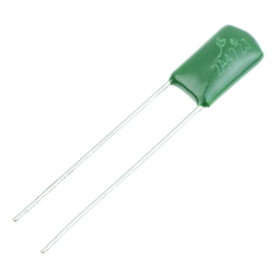
A 1nF capacitor, characterized by its 1 nanofarad (nF) capacitance, is a fundamental passive electronic component adept at storing electrical energy in an electric field. This component plays a crucial role in various electronic circuits, facilitating functions such as filtering, timing, and energy storage.
The value of 1nF places it within the range of small capacitance values, making it suitable for high-frequency applications and signal processing, distinguishing it from larger capacitors with microfarad or farad values that are primarily used for energy storage and low-frequency circuits. The physical size of a 1nF capacitor is usually small, with SMD (Surface Mount Device) being the most common, with various case sizes available.
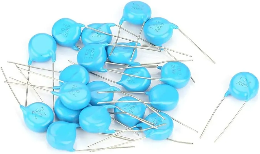
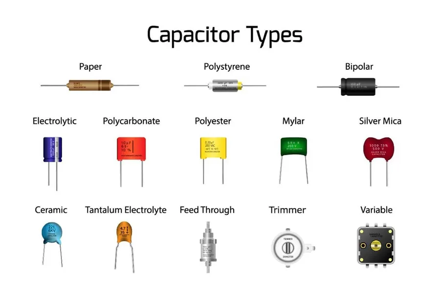
1nF capacitors, while seemingly small in capacitance, are available in several types, each suited for specific applications based on their construction and performance characteristics. The primary types include ceramic, film, and less commonly, electrolytic capacitors. Each type offers different advantages and disadvantages regarding size, cost, stability, and frequency response, influencing their suitability for different electronic circuits.
| Capacitor Type | Construction | Pros | Cons | Common Applications |
|---|---|---|---|---|
| Ceramic | Uses ceramic dielectric material, often multi-layered. | Small size, low cost, high-frequency performance. | Lower capacitance values, temperature and voltage dependence, can be microphonic. | Decoupling, filtering, general-purpose applications. |
| Film | Uses a thin plastic film as a dielectric, often with metal electrodes. | Good stability, high precision, low loss. | Larger size, generally more expensive. | Audio circuits, precision timing, high-frequency applications. |
| Electrolytic | Uses an electrolyte as one electrode and a thin metal oxide layer as the dielectric. | High capacitance values in small size | Polarized, poor high-frequency response, higher ESR. | Power supply decoupling, large energy storage. |
For 1nF capacitance, ceramic and film capacitors are the most prevalent choices. Ceramic capacitors, particularly multilayer ceramic capacitors (MLCCs), offer a compact and cost-effective solution for general-purpose use, with some trade-offs in terms of stability and precision. Film capacitors, in contrast, provide superior stability and precision, making them ideal for applications where performance consistency is paramount, often at a higher cost and larger size. Electrolytic capacitors are rarely encountered at 1nF values due to their design characteristics and the specific range of capacitance where their advantages are relevant.
Capacitor codes are essential for identifying their capacitance value, especially when the physical size is too small to print the value directly. For a 1nF capacitor, standard coding systems are used which often include a 3-digit numerical code that requires interpretation.
The most common coding system uses a 3-digit number, where the first two digits represent the significant figures of the capacitance value, and the third digit represents the multiplier. This multiplier is a power of 10. The capacitance value is always in picofarads (pF). A code of '102' indicates a capacitance of 10 x 10^2 pF, or 1000 pF, which is equivalent to 1 nF.
| Code | Calculation | Capacitance (pF) | Capacitance (nF) |
|---|---|---|---|
| 102 | 10 * 10^2 | 1000 | 1 |
| 103 | 10 * 10^3 | 10000 | 10 |
| 221 | 22 * 10^1 | 220 | 0.22 |
| 473 | 47 * 10^3 | 47000 | 47 |
| 151 | 15 * 10^1 | 150 | 0.15 |
Some capacitors also include tolerance codes. This is usually a letter indicating the allowable deviation from the stated capacitance. For example, 'J' indicates a tolerance of ±5%, 'K' indicates ±10%, and 'M' indicates ±20%. This information is often printed directly next to the numerical code.
It's important to note that not all capacitors follow this precise coding system. Some may use color bands or other methods for indicating the value. Always refer to the manufacturer's datasheet for clarification when needed.
Selecting the appropriate 1nF capacitor for a specific application requires a thorough understanding of its electrical specifications, primarily rated voltage and tolerance. These parameters significantly impact circuit performance and reliability, and deviations from the correct values can lead to component failure or circuit malfunction.
| Specification | Description | Impact on Circuit Performance |
|---|---|---|
| Rated Voltage | The maximum voltage that can be continuously applied across the capacitor without risking damage or failure. | Exceeding the rated voltage can lead to dielectric breakdown, short circuits, and permanent damage to the capacitor and other components. |
| Tolerance | The permissible deviation in actual capacitance from the nominal value (1nF in this case), often expressed as a percentage. | A capacitor with a high tolerance may deviate significantly from 1nF, causing variations in circuit timing, filter frequencies, and signal coupling. |
Understanding these specifications is crucial for ensuring optimal performance and longevity of electronic circuits. Manufacturers typically specify these parameters in datasheets, and engineers should carefully review them to select the appropriate capacitor for a given application. Consider a scenario where a 1nF capacitor with a 10% tolerance may result in an actual capacitance range of 0.9nF to 1.1nF; this is generally acceptable in many signal processing applications. Similarly, using a capacitor with a rated voltage lower than the actual voltage in the circuit could lead to catastrophic failure of the circuit.
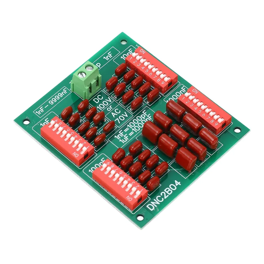
1nF capacitors, while seemingly small in capacitance, play crucial roles across a spectrum of electronic applications. Their ability to rapidly charge and discharge makes them ideal for tasks ranging from high-frequency filtering to precise timing and decoupling, ensuring stable and efficient operation of electronic circuits.
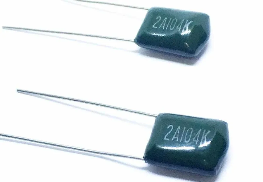
While a 1nF capacitor serves specific functions, understanding its role compared to other common values, such as a 100nF capacitor, is crucial for effective circuit design. The primary difference lies in their capacitance values, directly impacting their frequency response and charge storage capabilities.
| Feature | 1nF Capacitor | 100nF Capacitor |
|---|---|---|
| Capacitance | 1 nanofarad (1 x 10^-9 Farads) | 100 nanofarads (1 x 10^-7 Farads) |
| Charge Storage | Lower | Higher |
| Frequency Response | Effective at higher frequencies | Effective at lower to mid frequencies |
| Typical Applications | High-frequency filtering, timing circuits | Decoupling, noise suppression |
| Physical Size (Typically) | Smaller | Larger |
| Impedance (at a given frequency) | Higher impedance | Lower impedance |
A 1nF capacitor is better suited for high-frequency applications due to its lower capacitance, leading to a higher impedance at lower frequencies, which makes it less effective for decoupling power rails. Conversely, a 100nF capacitor's higher capacitance allows for greater charge storage, making it ideal for decoupling to stabilize voltage rails, reducing noise by providing a low impedance path to ground for unwanted AC signals, and is more appropriate in applications requiring larger charge storage and mid-range frequency filtering.
When choosing between a 1nF and 100nF capacitor, it's essential to consider the specific frequency range of the application. For high-speed digital circuits, 1nF capacitors may be used for fine-tuning filters, and smaller capacitive coupling, while 100nF capacitors are the workhorse of decoupling to prevent voltage fluctuations on the power rails and eliminate noise. Careful consideration of the application is important to utilize each capacitor to its maximum potential.
This section addresses common questions regarding 1nF capacitors, providing concise and technically accurate answers to clarify their properties and applications. We aim to clear up any confusion surrounding their specifications, markings, and usage.
Selecting the appropriate 1nF capacitor involves a careful evaluation of several factors to ensure optimal circuit performance and reliability. This includes considering the application's specific voltage requirements, operating temperature range, physical size constraints, and the material properties of the capacitor.
The following table outlines the key parameters to consider when selecting a 1nF capacitor:
| Parameter | Description | Considerations |
|---|---|---|
| Voltage Rating | The maximum voltage the capacitor can safely handle without failing. | Must exceed the maximum voltage expected in the circuit to prevent breakdown. |
| Tolerance | The acceptable deviation from the nominal capacitance value (1nF). | Choose a tighter tolerance for applications requiring precise timing or filtering. |
| Temperature Coefficient | Describes how capacitance changes with temperature. | Select a capacitor with a stable coefficient for applications with varying operating temperatures. |
| Package Type | The physical form factor of the capacitor (e.g., SMD, through-hole). | Select based on the PCB design and assembly method. |
| Material | The dielectric material used (e.g., ceramic, film, multilayer). | Influences the capacitor's performance characteristics, such as temperature stability and ESR (Equivalent Series Resistance). |
| Size | The physical dimensions of the capacitor. | Must fit within the available space on the circuit board. |
| Application | Specific use case, such as filtering, decoupling or timing. | Each application has different requirements of parameters. |
For example, in a high-frequency filtering application, a ceramic capacitor with a low ESR and stable temperature characteristics would be a suitable choice. Conversely, in a less demanding application, a general-purpose film capacitor might suffice. Consider both cost and performance when selecting the optimal 1nF capacitor.
1nF capacitors, while generally robust, can exhibit various failure modes that impact circuit performance. Understanding these issues, their diagnosis, and preventative measures is crucial for ensuring the reliability and longevity of electronic devices.
The 1nF capacitor, seemingly a small component, is a cornerstone of modern electronics. Whether you're designing a new circuit or troubleshooting an existing device, understanding its characteristics, applications, and variations is crucial. This article has shed light on the different types, markings, specifications, and uses of the 1nF capacitor, empowering you with the knowledge to effectively integrate it into your electronic designs and projects. By appreciating the role of even the smallest components, like the 1nF capacitor, we can better grasp the complexity and ingenuity of the technology that surrounds us. The 1nF capacitor is not just a component; it’s a critical element in the building blocks of technology.

