In the world of electronics, the 470uF 25V capacitor is a common yet crucial component. From smoothing out power supplies in everyday devices like TVs to filtering noise in audio circuits, its presence is often unseen but essential. This capacitor, with its 470 microfarads (uF) capacitance and 25-volt rating, serves as a workhorse, storing energy and regulating current in countless applications. This article will dive into the world of the 470uF 25V capacitor, explaining its function, types, applications, and practical tips for using and replacing it. Let's take a closer look at this fundamental building block of our electronic society.
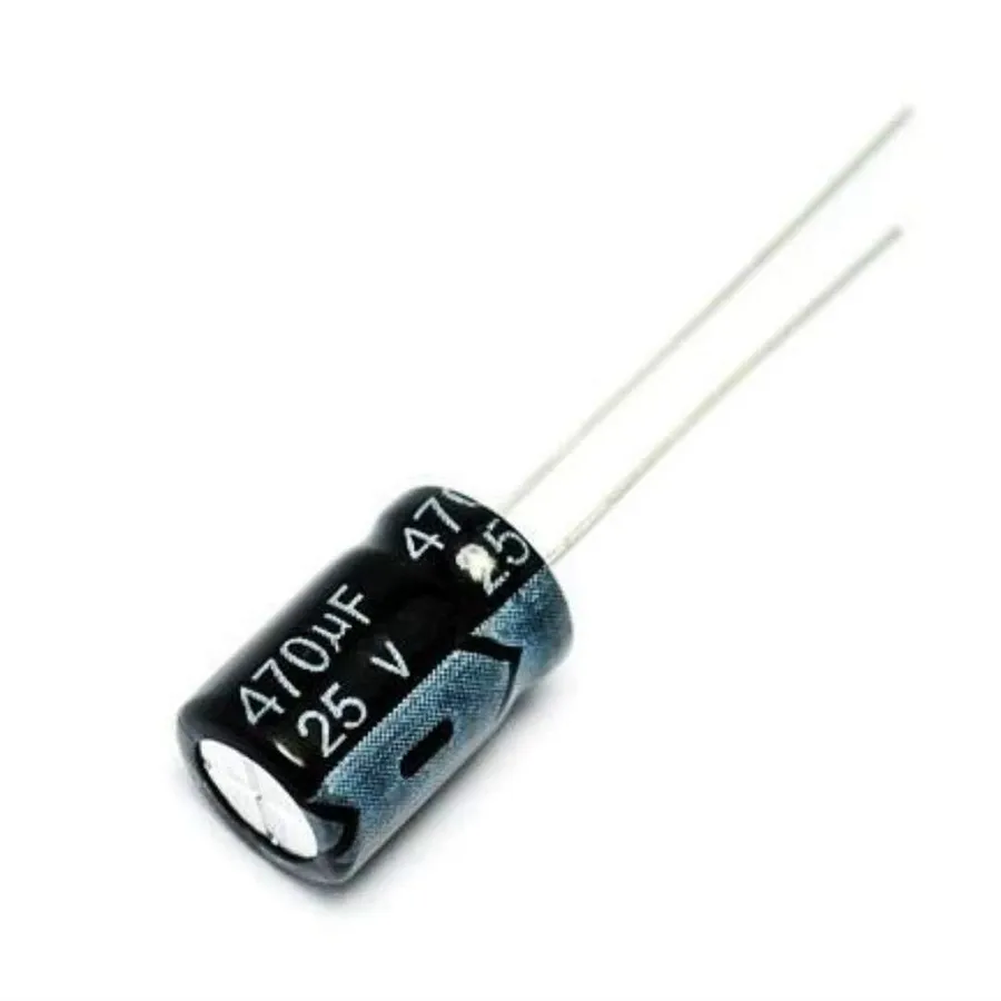
A 470uF 25V capacitor is a specific type of electronic component designed to store electrical energy temporarily. The '470uF' denotes its capacitance, a measure of its ability to store charge, specifically 470 microfarads. The '25V' indicates its maximum voltage rating, the highest voltage that can be safely applied across the capacitor without risk of failure. This particular capacitor is an electrolytic type, commonly used due to its high capacitance-to-volume ratio, but it's crucial to observe its polarity during circuit integration.
Capacitors, in essence, are fundamental components in electronic circuits, working like miniature rechargeable batteries. However, they differ from batteries in that they release their stored energy much faster and are primarily used for temporary energy storage and filtering applications rather than sustained power delivery. The 470uF 25V capacitor, owing to its specific capacitance and voltage rating, finds widespread use in many circuits where these parameters are optimal for its function, such as power supply smoothing and signal coupling.
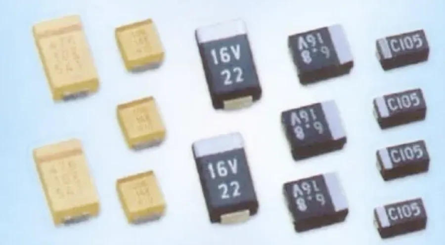
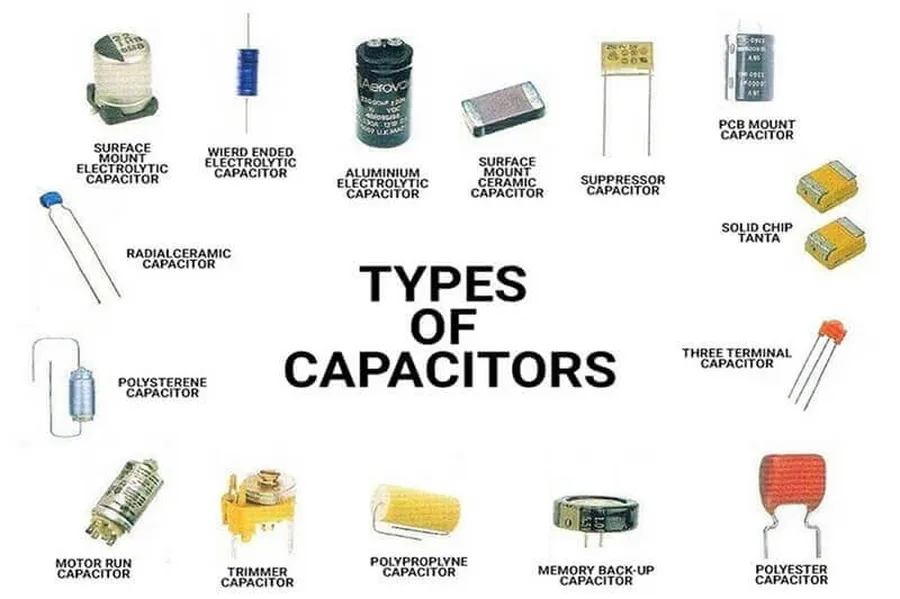
The 470uF 25V capacitor is available in several physical configurations, each designed for specific mounting and application requirements. Understanding these variations is crucial for selecting the correct component for a given electronic design. The primary types include radial lead, axial lead, and surface mount (SMD) capacitors.
| Capacitor Type | Physical Characteristics | Common Applications |
|---|---|---|
| Radial Lead | Leads extend from the same side of the capacitor body. Typically cylindrical with wire leads. | General-purpose applications, through-hole mounting on printed circuit boards (PCBs). Suitable for prototyping and breadboarding. |
| Axial Lead | Leads extend from opposite ends of the capacitor body. Often cylindrical or tubular. | Older designs, point-to-point wiring, less common in modern PCB assemblies. Useful where space constraints require a linear layout. |
| Surface Mount (SMD) | Small, rectangular or cylindrical packages with terminals designed to be soldered directly to the surface of a PCB. | High-density PCB designs, automated assembly processes. Widely used in consumer electronics and modern devices. |
Understanding the key specifications and parameters of a 470uF 25V capacitor is crucial for selecting the correct component for a given application and ensuring optimal circuit performance. These parameters define the capacitor's behavior and limitations within an electronic circuit. Key specifications include capacitance, voltage rating, tolerance, temperature rating, equivalent series resistance (ESR), and leakage current.
| Parameter | Description | Typical Values for 470uF 25V Capacitor |
|---|---|---|
| Capacitance | The ability of a capacitor to store an electrical charge. Measured in microfarads (uF). | 470 uF |
| Voltage Rating | The maximum voltage that can be safely applied across the capacitor without damaging it. | 25 V |
| Tolerance | The allowable deviation of the actual capacitance value from its nominal value. Usually expressed as a percentage. | ±20% |
| Temperature Rating | The range of operating temperatures that the capacitor can withstand without degradation. Expressed in degrees Celsius. | 85°C, 105°C (Common) |
| ESR (Equivalent Series Resistance) | The internal resistance of the capacitor, which affects its performance at high frequencies. Measured in ohms (Ω). | Varies, typically < 1 Ω |
| Leakage Current | The small current that flows through the capacitor's dielectric even when no voltage is applied. Measured in microamperes (μA) | Varies, typically < 50μA |
These parameters are typically specified in the capacitor's datasheet, which is an essential resource for engineers and technicians. A deeper understanding of these specifications will help to choose the most appropriate capacitor for the circuit design. When selecting a capacitor, consider the operating environment and the specific demands of the application. For instance, a capacitor operating in a high-temperature environment requires a higher temperature rating, and high-frequency applications often necessitate capacitors with low ESR.
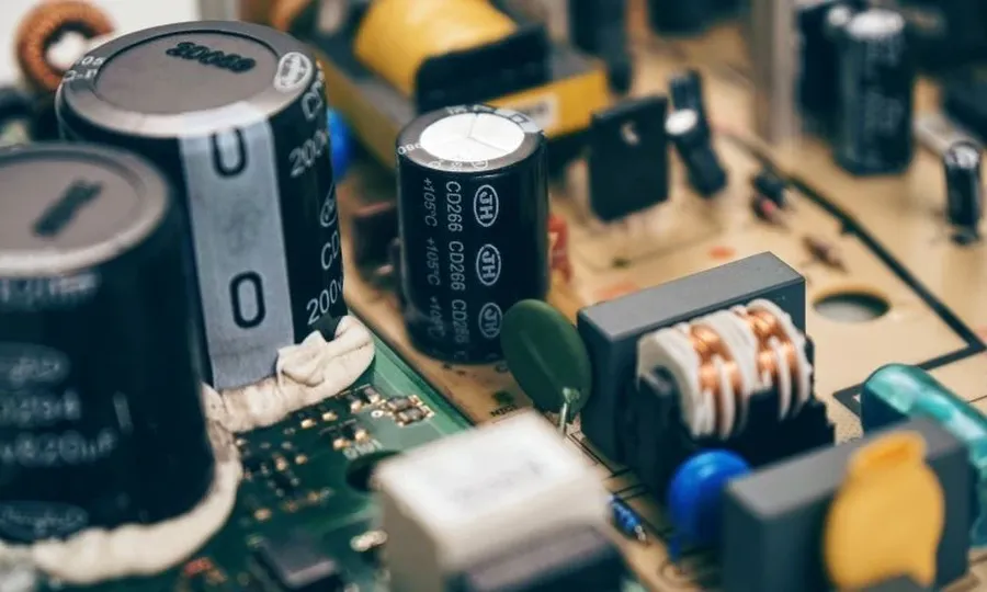
The 470uF 25V capacitor is a versatile component widely employed in numerous electronic devices due to its effective energy storage and filtering capabilities. Its moderate capacitance and voltage rating make it suitable for a range of applications where smoothing, decoupling, and signal coupling are critical. This section details the common applications where this capacitor is frequently utilized.
Key Applications:
Selecting the appropriate 470uF 25V capacitor for a specific application requires careful consideration of several factors to ensure optimal performance and longevity of the electronic device. Key parameters include physical size constraints, operating temperature, expected lifespan, and the required tolerance.
| Selection Criteria | Considerations | Impact on Application |
|---|---|---|
| Physical Size | Available space on the circuit board; dimensions (diameter, height, lead spacing). | Ensures component fits within device enclosure without interference. |
| Operating Temperature | Ambient temperature range of the device's environment; capacitor's temperature rating (e.g., 85°C, 105°C). | Prevents premature failure due to excessive heat exposure, ensuring reliable operation. |
| Life Expectancy | Desired operational lifespan of the device; capacitor's rated lifetime (e.g., 2000 hours, 5000 hours). | Guarantees long-term performance and reduces the need for frequent component replacements. |
| Tolerance | Acceptable variance from the nominal capacitance (e.g., ±20%); precision needed in the application. | Maintains circuit stability and accuracy within acceptable parameters. |
Additionally, the capacitor's equivalent series resistance (ESR) and ripple current rating must be taken into account for demanding applications, as these parameters directly impact heat dissipation and overall stability. Always consult the component's datasheet for accurate specifications and performance characteristics. Furthermore, the dielectric material of the capacitor (e.g., aluminum electrolytic, ceramic) may also be a consideration, based on application specifics and cost.
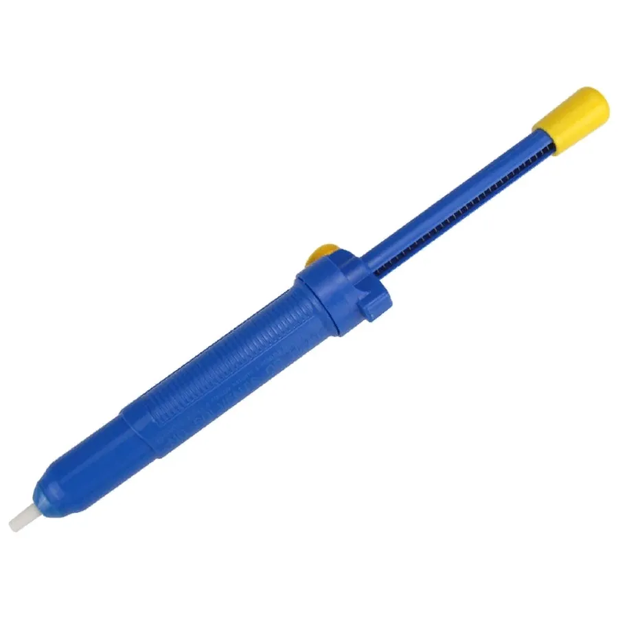
Replacing a faulty 470uF 25V capacitor requires careful attention to detail and adherence to safety protocols. This section provides a step-by-step guide to ensure a successful and safe replacement process.
While a 470uF 25V capacitor is designed for specific applications, situations may arise where an alternative is needed. This section explores the viability of using different voltage ratings, specifically 470uF capacitors with 16V and 35V ratings, and discusses the implications of such substitutions. The primary focus is on the safe and effective selection of replacement capacitors.
| Characteristic | 470uF 25V Capacitor | 470uF 16V Capacitor | 470uF 35V Capacitor |
|---|---|---|---|
| Capacitance | 470uF | 470uF | 470uF |
| Voltage Rating | 25V | 16V | 35V |
| Suitability as direct replacement | Ideal | Limited - lower voltage | Viable - higher voltage |
| Impact on performance | Optimal | May cause failure at higher voltage levels | Typically No adverse effects |
| Cost | Standard | Potentially less expensive | Potentially more expensive |
A critical consideration when replacing capacitors is their voltage rating. A capacitor with a voltage rating *lower* than the original, such as the 470uF 16V, should **never** be used as a direct replacement. This is because, in circuits where the voltage exceeds 16V, this capacitor may experience dielectric breakdown. This could lead to capacitor failure, potential damage to the circuit, or even become a safety hazard. However, using a capacitor with a *higher* voltage rating such as 470uF 35V is generally permissible and offers a safety margin. This higher voltage capacitor is more robust and can withstand the original circuit's voltage demand. The trade-off is that these may be slightly larger physically and could come with a higher cost.
This section addresses common questions about 470uF 25V capacitors, providing clear and concise answers to enhance understanding and ensure safe handling practices when working with these components.
In conclusion, the 470uF 25V capacitor is a foundational electronic component used in countless applications, playing a crucial role in device functionality and reliability. Whether it's smoothing power delivery or filtering signals, its function is fundamental to modern electronic circuits. Understanding the capacitor’s specifications, applications, and the considerations involved in selection and replacement is essential for anyone working with or repairing electronic devices. When considering purchasing or replacing a 470uF 25V capacitor, remember to consider the type, size, temperature rating and voltage requirements to ensure optimal performance and safety. By understanding and following these best practices, you can ensure the continued smooth operation of your electronic devices.

