Understanding the 5V Zener Diode: Uses, Selection, and Circuit Design
2025.02.06
From smartphones to industrial equipment, electronic circuits rely on precise voltage regulation. The 5V zener diode acts as a vital component, efficiently maintaining voltage levels at 5V. This article delves into the functionality of 5V zener diodes, their diverse uses, selection criteria, and design considerations, shedding light on their importance in modern electronics.
What is a 5V Zener Diode and How Does It Work?
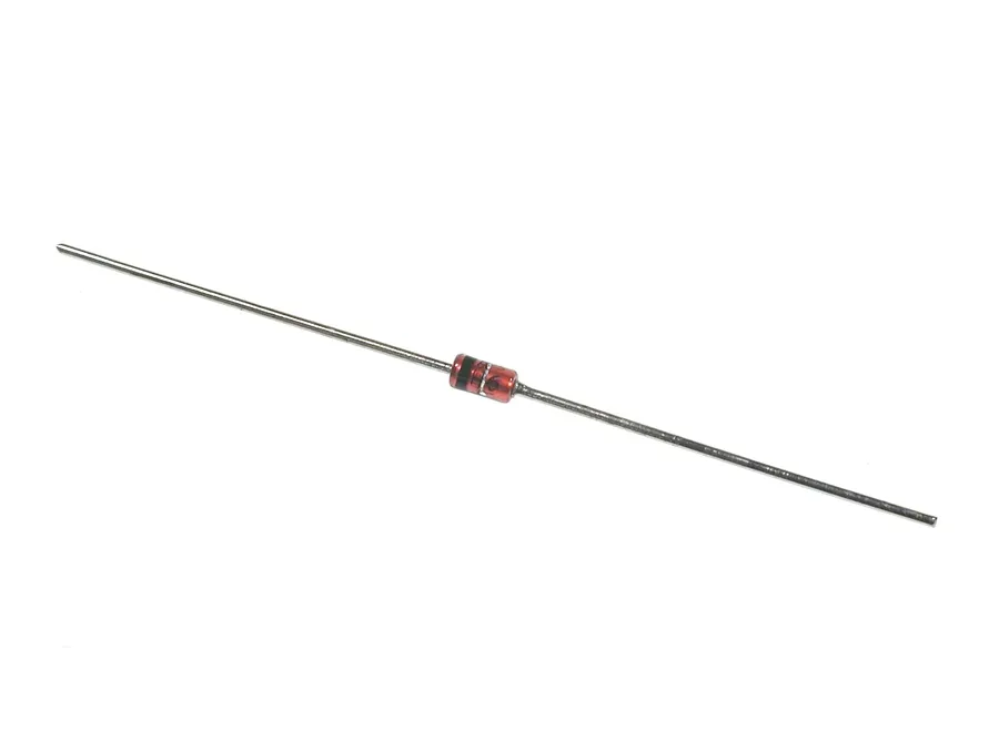
5V Zener Diode
A 5V Zener diode is a specialized type of semiconductor diode engineered to maintain a consistent voltage drop of approximately 5 volts across its terminals when operated in reverse bias mode, specifically when the applied reverse voltage reaches its designed breakdown voltage. This behavior contrasts with that of a standard diode, which primarily conducts current in the forward direction.
The fundamental principle behind a Zener diode's operation hinges on the Zener effect, a quantum mechanical phenomenon where a strong electric field across the diode's depletion region allows electrons to tunnel through the potential barrier when the reverse voltage exceeds a certain threshold. This controlled breakdown permits the diode to conduct in the reverse direction while maintaining a stable voltage, making it ideal for voltage regulation and protection.
In essence, a 5V Zener diode is designed to ‘break down’ at 5V when reverse biased, clamping the voltage to approximately 5V, this contrasts with a standard diode, which blocks reverse current until damaged. This behavior is not a failure but a design feature of the Zener diode.
Key Parameters and Specifications of a 5V Zener Diode
Understanding the key parameters of a 5V Zener diode is crucial for its effective application. These parameters define the diode's performance characteristics and limitations. The most important specifications include the nominal Zener voltage, power dissipation rating, Zener impedance, and tolerance, each significantly affecting circuit behavior.
Parameter
Description
Significance
Typical Values for 5V Zener (e.g., 1N4733A)
Nominal Zener Voltage (Vz)
The reverse voltage at which the diode starts conducting significantly. Specified as 5V for this device.
Determines the voltage regulation level; the Zener maintains a near-constant voltage drop near this value.
5V
Power Dissipation (Pd)
The maximum power the diode can safely dissipate as heat, determined by its physical structure and thermal resistance.
Exceeding this rating can lead to overheating and diode failure. Needs to be adequate for the current flow.
1W
Zener Impedance (Zz)
The resistance to a change in current once the Zener is in the breakdown region. Measured at a specific test current.
Lower Zener impedance results in a better voltage regulation.
7 Ω
Tolerance
The variation of the nominal Zener voltage from its specified value.
Lower tolerance values give more precise voltage regulation.
±5%
Test Current (Izt)
The current at which the Zener voltage is measured.
The Zener voltage varies with the current, so Izt provides a reference point.
76mA
Reverse Leakage Current (Ir)
Small current that flows through the diode in reverse bias before the Zener breakdown.
Indicates the degree of non-ideality of the Zener diode and affects performance.
5 µA
For instance, the 1N4733A is a common 5V Zener diode. It has a nominal Zener voltage of 5V, a power dissipation rating of 1 Watt, and a Zener impedance of approximately 7 ohms. Understanding and considering these parameters is critical in ensuring effective and reliable circuit design using 5V Zener diodes.
Common Applications of 5V Zener Diodes
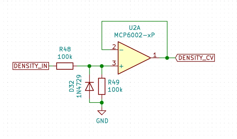
Zener Diode Application
5V Zener diodes are versatile components with a range of applications, primarily leveraging their ability to maintain a stable voltage drop at approximately 5V when reverse-biased. This characteristic makes them invaluable for overvoltage protection, voltage referencing, and signal clipping or limiting in various electronic circuits.
Overvoltage Protection Zener diodes are frequently employed to safeguard sensitive circuit components against excessive voltage. By placing a 5V Zener diode in parallel with the component to be protected, any voltage exceeding 5V will be shunted to ground through the diode, effectively clamping the voltage to a safe level. This is particularly crucial for protecting integrated circuits and other voltage-sensitive parts from damage caused by power surges or voltage spikes. Consider a scenario where a microcontroller is powered by a 5V source; a 5V Zener diode can prevent the microcontroller from being exposed to voltages higher than 5V.
Voltage Reference Circuits The consistent voltage drop of a 5V Zener diode makes it suitable for creating stable voltage references. These references are essential for accurate measurements and controls in various electronic systems, such as analog-to-digital converters (ADCs) and operational amplifiers. In this configuration, the diode is often used with a series resistor, and the Zener voltage serves as a dependable reference point for comparing and setting voltages within a circuit. A precise voltage reference is often needed for sensors and data acquisition systems to maintain the precision of the measurements.
Clipping and Limiting Circuits Zener diodes can be used to clip or limit the amplitude of signals. When a signal exceeds the Zener voltage, the diode begins to conduct, effectively limiting the signal's voltage. This is useful in applications such as wave shaping and signal processing. For instance, in audio circuits, Zener diodes can be employed to prevent signal peaks from overloading subsequent stages, ensuring signal integrity and dynamic range.
Selecting the Right 5V Zener Diode for Your Project
Zener Diode Packages
Selecting the appropriate 5V Zener diode for a project requires careful consideration of several key factors to ensure optimal performance and circuit reliability. The primary considerations revolve around the diode's electrical characteristics, physical packaging, and environmental tolerances, all of which must align with the intended application.
Key considerations when selecting a 5V Zener diode:
Power Dissipation Rating The power rating indicates how much power the diode can safely dissipate as heat. Calculate the maximum power the diode will experience in the circuit (Power = Voltage * Current) and select a diode with a rating that exceeds this value. Exceeding the power rating can lead to overheating and failure. For instance, a 1N4733A has a power rating of 1W which is a common choice.
Tolerance Zener diodes have a tolerance rating that specifies the deviation from the nominal Zener voltage. Common tolerances are 5% and 10%. For precise voltage regulation or reference applications, select a diode with a tight tolerance. For instance, a 5% tolerance on a 5V Zener could mean the actual voltage is between 4.75V and 5.25V. You should choose diodes with tighter tolerances if variations are unacceptable in your application.
Zener Impedance Zener impedance represents the change in voltage for a change in current, the lower the impedance, the better the Zener diode will maintain a constant voltage. This factor is particularly crucial in voltage regulation circuits. A lower Zener impedance indicates a more stable voltage output. Datasheets provide specific impedance values.
Operating Temperature Range Consider the operating environment of your project. Zener diodes are specified to operate within a certain temperature range. Ensure that the diode is rated to withstand the temperature fluctuations expected in your application. If a circuit is subject to extremes of temperature a lower tolerance and higher power rating may be required.
Package Type The choice between Surface Mount Devices (SMD) and through-hole packages depends on your project's assembly needs and space constraints. SMD components are suitable for compact designs and automated assembly, while through-hole components are easier for prototyping and manual assembly. Ensure your layout will support the choice of package.
Datasheet Analysis Always consult the datasheet for detailed specifications of your chosen Zener diode model. Pay close attention to the I-V (current-voltage) curves, the test current used to measure the Zener voltage and maximum ratings. These values are essential for reliable circuit design.
Practical tips for interpreting datasheets:
Nominal Zener Voltage (Vz) This is the specified reverse breakdown voltage of the Zener diode, ideally 5V for a 5V Zener diode. However, check the datasheet for the precise voltage value as it may have some variation. Also, check the test current at which this voltage is measured. For example, a 1N4733A has a nominal Zener voltage of 5.1V with a test current of 76mA.
Dynamic Impedance (Zz) This impedance impacts the stability of the voltage regulation. A lower impedance results in a more stable output. Often specified at the test current for Vz.
Reverse Leakage Current (Ir) This is the current that flows when the diode is reverse-biased below the Zener voltage. Ideally, it is very small. The datasheet will often specify at a fixed reverse voltage.
Power Dissipation (Pd) The maximum power the diode can dissipate safely. Make sure to select a diode where the calculated power in the circuit is below this number. This is typically given at a specific ambient temperature, and a derating factor will be given to compensate for higher temperatures.
Temperature Coefficient This indicates how the Zener voltage changes with temperature. This will influence your voltage regulation accuracy at different temperatures. Lower values are better.
5V Zener Diode Circuit Design and Considerations
Zener Voltage Divider
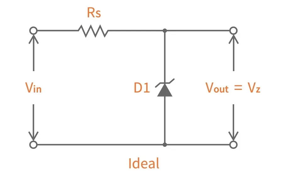
Designing circuits with a 5V Zener diode involves understanding its reverse-bias behavior and incorporating a series resistor to manage current flow. The primary function of the series resistor is to limit the current through the Zener diode, preventing it from exceeding its power dissipation rating and ensuring proper voltage regulation. The appropriate sizing of this resistor is critical for optimal circuit performance and component longevity.
Zener diodes are not designed for high power regulation, their ability to regulate voltage is limited by their power rating, they work best in low current and low power circuit design. There are three basic circuits that utilize Zener diodes: voltage regulation, overvoltage protection, and signal clipping.
Voltage Regulation Circuit In a basic voltage regulator circuit, the Zener diode is connected in reverse bias across the load, with a series resistor connected to the power supply. The resistor limits the current flow when the Zener is in breakdown and, thus, protects the diode from self destruction and ensures that voltage is regulated around the Zener breakdown voltage. The load, then, receives an approximately constant voltage, at the zener breakdown voltage, even as input voltage varies.
Overvoltage Protection Circuit A Zener diode can be used to protect sensitive circuits from overvoltage conditions. It’s placed in parallel with the component you are trying to protect, when the voltage exceeds the Zener's breakdown voltage, the diode begins to conduct, effectively clamping the voltage and preventing damage to the protected circuit. This protection mechanism works because the Zener only starts conducting over its Zener voltage, which is usually higher than the working voltage of the circuit.
Signal Clipping Circuit Zener diodes can also be used in signal clipping or limiting circuits, in these circuits, the Zener diode is used to limit the amplitude of a signal to a certain voltage, this is done by combining two Zener diodes, which are placed in back to back configuration which provides both positive and negative signal clipping.
Incorrectly sized series resistors can have detrimental effects. If the resistance is too low, excessive current will flow through the Zener diode, leading to overheating and potentially damaging the component or causing premature failure. Conversely, if the resistance is too high, the Zener diode may not enter its breakdown region, resulting in inadequate voltage regulation or protection. The proper resistor value is calculated based on the input voltage, the desired Zener current, and the diode's characteristics, which are usually provided in the datasheet.
Frequently Asked Questions About 5V Zener Diodes
This section addresses common queries regarding 5V Zener diodes, clarifying their operational characteristics and practical usage.
What is the typical tolerance of a 5V Zener diode? The typical tolerance for a 5V Zener diode is usually around ±5%, but can range from ±1% to ±10%. This tolerance indicates the deviation from the nominal 5V breakdown voltage. For precision applications, it's important to check the datasheet for the specific tolerance of the selected part.
What is the maximum reverse voltage a 5V Zener diode can withstand? A 5V Zener diode is designed to operate in reverse bias with a breakdown voltage of approximately 5V. The maximum reverse voltage it can withstand is typically specified in the datasheet as the maximum reverse working voltage. Exceeding this voltage will cause excessive current flow and may result in damage to the diode. This voltage is always higher than the breakdown voltage. It's critical to design the circuit to never exceed this value.
How can I test a 5V Zener diode? A 5V Zener diode can be tested using a multimeter in diode test mode. In the forward direction, it will behave like a normal diode with a voltage drop of about 0.7V. In the reverse direction, when a voltage higher than 5V is applied (through a current limiting resistor), it should exhibit a voltage drop of around 5V if it is functioning correctly. You can also use a power supply and series resistor to test at the design current to verify its characteristics.
How does a 5V Zener diode compare to a 5.1V Zener diode? The difference between a 5V and a 5.1V Zener diode is primarily in their breakdown voltage. A 5V Zener maintains a voltage around 5V while a 5.1V Zener maintains a voltage around 5.1V. The selection depends on the required voltage reference in the application. While the difference seems small, it can be crucial in precision circuits. Datasheets for each device must be consulted for precise characterization.
Can a 5V Zener diode be used as a voltage regulator? Yes, a 5V Zener diode can be used as a basic voltage regulator, particularly in low-current applications. It maintains a relatively constant voltage drop across it when reverse biased beyond its breakdown voltage, thereby providing a crude method of voltage regulation. However, its performance is significantly affected by changes in current and it is not as precise as a dedicated linear voltage regulator.
What is the power dissipation rating of a 5V Zener diode and why is it important? The power dissipation rating of a Zener diode specifies the maximum amount of power (in watts) it can safely handle without overheating and being damaged. It is the product of the current through the diode and the voltage across it. It's crucial to choose a diode with a power rating that exceeds the expected power dissipation in the circuit, by a safety margin. Overheating can lead to premature failure.
What is the Zener impedance and its effect on circuit performance? Zener impedance is the small, but not zero, resistance of the Zener diode when operated in its breakdown region. This impedance leads to a small change in the Zener voltage as the current through the diode changes. Lower Zener impedance means a more stable output voltage. A lower impedance results in better regulation as the load current changes. Datasheets will often specify the test conditions for the Zener impedance.
5V Zener Diode vs. Linear Voltage Regulators
Zener vs Linear Regulator
While both 5V Zener diodes and linear voltage regulators can provide a stable voltage, they operate on different principles and have varying characteristics, making them suitable for different applications. Understanding their distinctions is crucial for efficient circuit design. Zener diodes are primarily shunt regulators and are simpler but less precise and efficient, whereas linear regulators are series regulators offering better precision and efficiency at the cost of higher component count and complexity.
Feature
5V Zener Diode
Linear Voltage Regulator
Regulation Type
Shunt regulator
Series regulator
Voltage Accuracy
Moderate (typically 5% tolerance)
High (typically 1-2% tolerance, or adjustable)
Efficiency
Low (power is dissipated as heat, especially with higher currents)
Moderate to High (more efficient at lower voltage drops)
Cost
Low
Moderate to High
Complexity
Simple, requires minimal external components
More complex, often requires additional components like capacitors
Current Handling
Limited by power dissipation rating
Wider range of current handling capabilities, with specific regulator types
Temperature Sensitivity
Moderate to high dependency, voltage can drift with temperature
Lower temperature drift and more precise temperature compensation available
Application Suitability
Overvoltage protection, simple voltage reference
Stable voltage supply for ICs and sensitive circuitry
Power Dissipation
High, especially with a load drawing significant current
Lower if the voltage drop is small.
Identifying 5V Zener Diodes and Common Markings
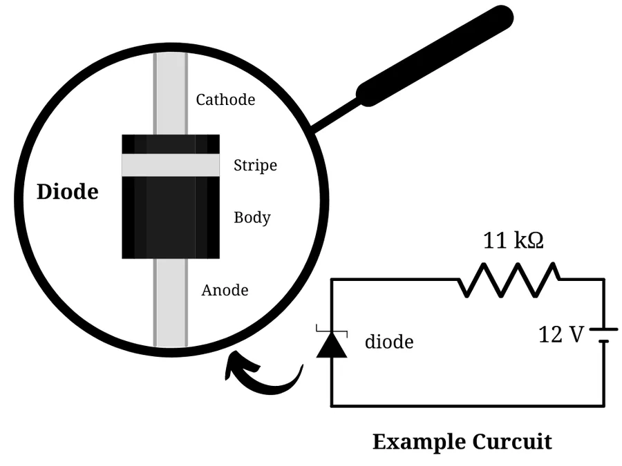
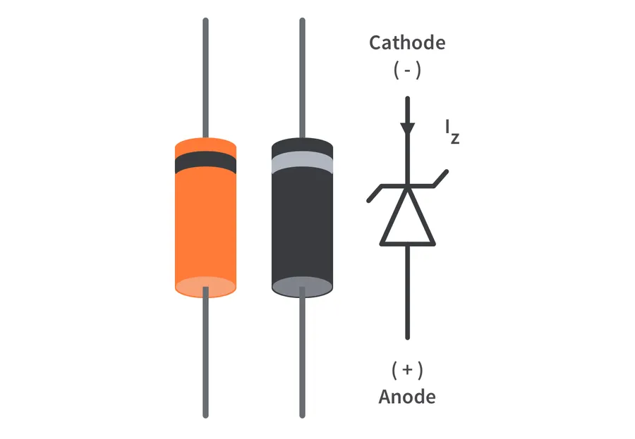
Zener Diode Markings
Identifying a 5V Zener diode correctly is crucial for effective circuit design and troubleshooting. These diodes are typically identified by their markings, package type, and physical characteristics. Understanding the coding systems and common markings ensures you select the correct component for your application.
Zener diodes, including 5V variants, generally use standardized part numbering systems. The most common identification system is the '1N' series, followed by a number specifying the diode's characteristics. For example, the 1N5231 series diodes are commonly used as 5V Zener diodes, but 1N4733A is also a common part number for a 5V Zener diode. The 'A' suffix in this example generally denotes a tighter voltage tolerance. Some manufacturers may also utilize their own unique coding systems in addition to or instead of the 1N series.
Package Type Zener diodes are available in various packages, including through-hole (e.g., DO-35, DO-41) and surface-mount (SMD) packages (e.g., SOD-123, SOD-323, SOT-23). The physical size and shape of the package can provide a clue to the diode's specifications, but part number markings are more accurate for identifying the exact device.
Part Number Marking The part number is typically printed directly on the body of the diode. For through-hole components, this is often in an easily readable format, while SMD components may have a more concise code. The marking may include the series code (e.g., '1N') followed by the specific device number. In certain cases, the marking may also include a letter suffix which indicates tolerance grade.
Color Banding (Older Devices) Older diodes may use color bands to indicate their characteristics, similar to resistors. However, this method is less common for modern Zener diodes. Consult a specific Zener diode datasheet or a reference chart to decipher color coding.
Marking Example
Description
Package Type
1N4733A
A common 5V Zener diode, often with 5% tolerance
DO-41
1N5231B
A 5.1V Zener diode that can sometimes be misidentified as a 5V zener
DO-35
C30
A marking commonly used on a 5V Zener diode in a small SMD package
SOD-323
When identifying a 5V Zener diode, it's essential to cross-reference the markings with the manufacturer's datasheet. Variations in marking schemes may exist, so the datasheet is the definitive source of information. Furthermore, when using SMD components, sometimes it is easier to identify the correct component using a multimeter to measure the voltage when the diode is placed into reverse bias.
Practical Tips and Troubleshooting
Effective utilization of 5V Zener diodes requires understanding their limitations and potential failure modes. This section provides practical tips, common issues, and troubleshooting techniques to ensure reliable circuit operation, focusing on preventing overheating, managing excessive current, and addressing component failures.
Tip 1: Verify Zener Diode Power Dissipation Always check the power dissipation rating of the 5V Zener diode. Ensure the actual power dissipated in the circuit is less than the diode's rating to prevent overheating. Use the formula P = V * I (Power = Voltage * Current) to calculate the power and select appropriately.
Tip 2: Employ a Series Resistor Use a series resistor in a Zener diode circuit to limit the current. An incorrectly sized resistor can lead to the Zener diode exceeding its power rating and overheating. Use Ohm's Law to accurately calculate the required resistance.
Tip 3: Consider Thermal Management If the 5V Zener diode operates at a high power level, consider using a heat sink to dissipate excess heat. This can prevent thermal runaway and ensure the component stays within its operating temperature range.
Tip 4: Use a Multimeter to Validate Operation Use a multimeter to measure the voltage across the Zener diode. If the voltage is not close to 5V under normal reverse bias, there may be an issue with the diode or the circuit, verify the series resistor value, and the input voltage.
Tip 5: Be Mindful of Reverse Current Be cautious of the reverse current through the Zener diode, as excessive current can cause it to overheat and fail. If possible, measure the reverse current using a multimeter and compare to its datasheet value.
Tip 6: Monitor Temperature Sensitivity Zener diodes are temperature-sensitive, with the voltage varying slightly with temperature fluctuations. Consider this in designs and use a zener diode that has low temperature coefficients if this affects the circuit performance.
Tip 7: Component Placement Ensure the Zener diode is correctly oriented in the circuit, as reversed polarity will damage the component. Use a Zener with clear marking to ensure correct placement in the circuit
Tip 8: Inspect Soldering Joints Inspect soldering joints to make sure no solder bridges, and it is well connected to the circuit. Bad connections can lead to poor circuit performance.
The 5V zener diode is a versatile component, essential for precise voltage regulation and protection in many electronic circuits. Understanding their functionality, parameters, and application best practices enables electronic enthusiasts and professionals alike to harness the full potential of this component. From stabilizing reference voltages to safeguarding delicate circuits, the 5V zener diode plays an indispensable role. Future advancements may see further improvements in their efficiency and temperature stability, making them an even more critical element in electronics engineering.