In our increasingly power-hungry world of electronics, the humble voltage regulator IC is the unsung hero ensuring devices run smoothly. Like a traffic controller for electricity, these ICs maintain a stable output voltage despite fluctuations in input or load. Whether it's the microcontroller in your smart watch or the power supply in your computer, understanding voltage regulator ICs is crucial for anyone working with electronic systems. This article will navigate through the intricacies of voltage regulator ICs, exploring their types, working principles, selection criteria and practical applications, providing the knowledge needed to choose the right component for your specific needs.
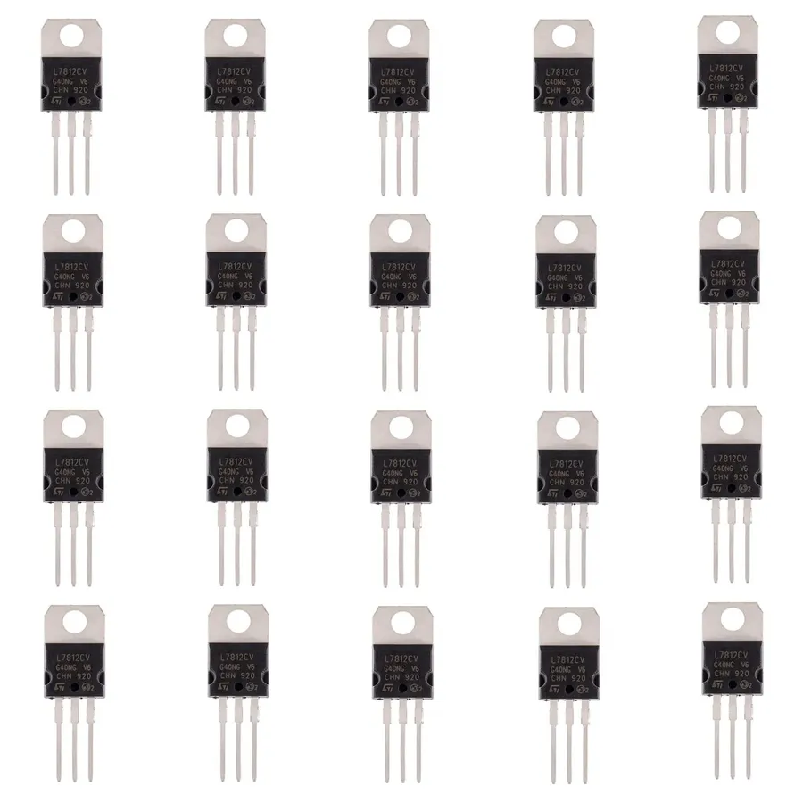
A voltage regulator IC is a crucial electronic component designed to automatically maintain a stable output voltage, regardless of variations in the input voltage or the load current. At its core, it ensures that connected devices receive a consistent and reliable power supply, preventing damage from over or under-voltage conditions. This capability is fundamental in a wide array of applications, from simple electronic circuits to complex industrial systems.
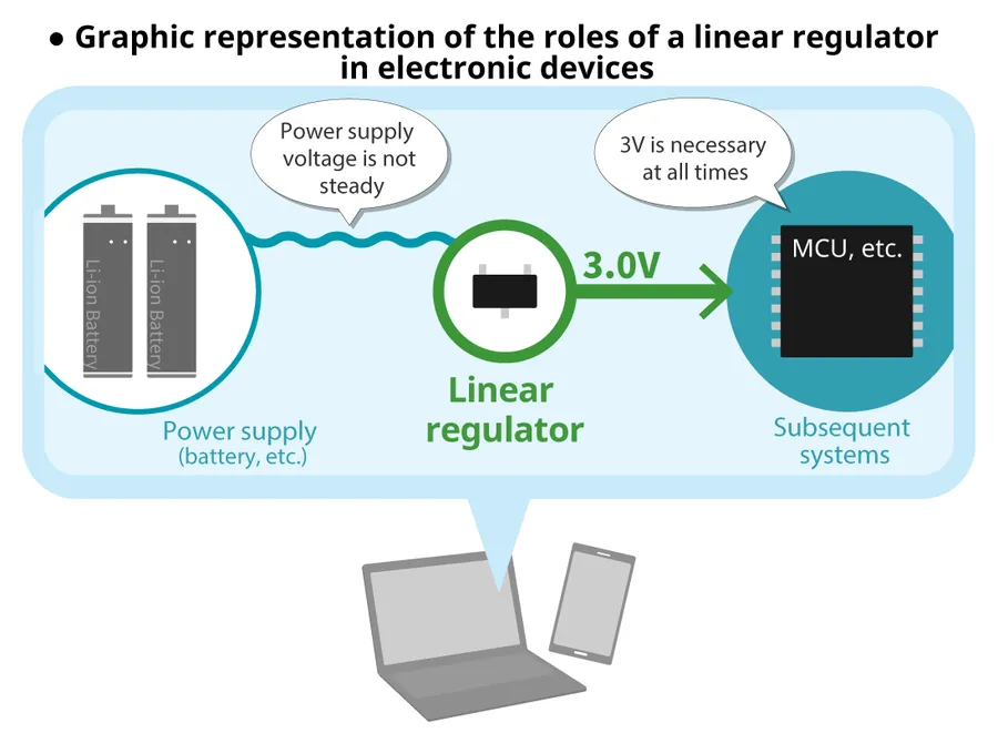
Linear regulators, often referred to as Low Dropout Regulators (LDOs), function by dissipating excess voltage as heat to maintain a stable output voltage. They operate by using a pass transistor in its linear region, adjusting the resistance to drop the input voltage to the desired output level. This method is fundamentally simple, resulting in circuits that are easy to design and implement, and they also produce very low output noise, making them suitable for sensitive electronic applications. However, this approach comes with inherent inefficiencies, particularly when there is a large difference between the input and output voltages, leading to significant heat generation, which requires careful thermal management. This heat generation is the primary cause for the reduced efficiency of linear regulators, limiting their use in high power applications.
A comparative analysis of key parameters is essential when selecting the appropriate voltage regulator IC for a given application. This section provides a structured comparison of several common voltage regulator ICs, highlighting their distinct characteristics. These parameters include input voltage range, output voltage, output current, dropout voltage, efficiency, and thermal resistance, among others. Understanding these differences is critical for optimal circuit design and performance.
| Parameter | 7805 (Fixed Linear) | 7812 (Fixed Linear) | LM317 (Adjustable Linear) | LM2596 (Buck Switching) |
|---|---|---|---|---|
| Input Voltage Range | 7V - 35V | 14.5V - 35V | 3V - 40V | 4.5V - 40V |
| Output Voltage | 5V Fixed | 12V Fixed | 1.25V to 37V (Adjustable) | 1.23V to 37V (Adjustable) |
| Output Current | Up to 1A | Up to 1A | Up to 1.5A | Up to 3A |
| Dropout Voltage | ~2V | ~2V | ~2V | N/A |
| Efficiency | Low (30-60%) | Low (30-60%) | Low (30-60%) | High (70-90%) |
| Switching Frequency | N/A | N/A | N/A | 150 kHz |
| Quiescent Current | ~5mA | ~5mA | ~5mA | ~3mA |
| Thermal Resistance | High (Thermal Management Required) | High (Thermal Management Required) | High (Thermal Management Required) | Low (Usually needs Heatsink) |
| Topology | Linear | Linear | Linear | Switching Buck |
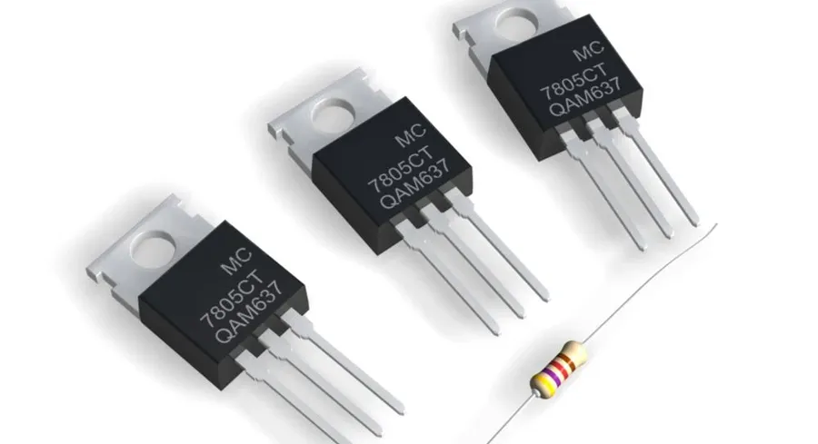
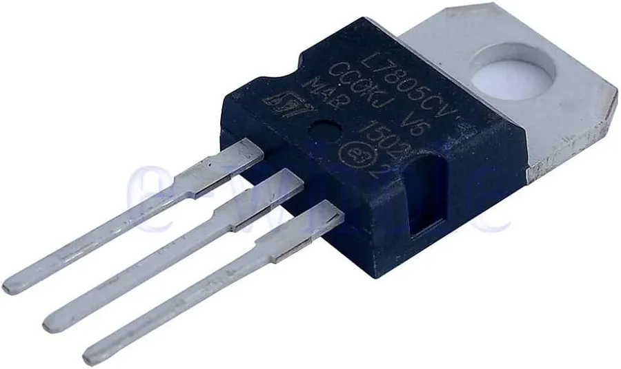
The 7805 and 7812 series are ubiquitous three-terminal linear voltage regulators, renowned for their simplicity and reliability in providing fixed positive voltage outputs. The 7805 provides a +5V output, while the 7812 provides +12V. Their ease of use makes them a staple in various electronic circuits, from hobbyist projects to industrial applications.
| Feature | 7805 | 7812 |
|---|---|---|
| Output Voltage | +5V | +12V |
| Input Voltage Range | 7V to 25V | 14.5V to 30V |
| Maximum Output Current | 1A (typically) | 1A (typically) |
| Package Type | TO-220, TO-252, TO-92 | TO-220, TO-252, TO-92 |
It's important to note that, like all linear regulators, the 78XX series generates heat as a byproduct of voltage regulation. Proper heat sinking is crucial to ensure these regulators operate within their temperature limits, especially when dealing with higher input voltage differentials or larger output currents. Datasheets from manufacturers like Texas Instruments and STMicroelectronics provide detailed thermal specifications and guidelines for optimal performance.
Voltage regulator ICs are essential components in electronic circuits, ensuring a stable voltage supply. They fall into two primary categories: linear regulators and switching regulators, each with distinct operational mechanisms, advantages, and limitations. Understanding these differences is crucial for selecting the appropriate regulator for a specific application. This section provides an in-depth overview of these types, focusing on their key characteristics and how they operate.
Linear regulators, especially Low-Dropout regulators (LDOs), function by reducing the input voltage to the desired output voltage, with the excess voltage being dissipated as heat. This method ensures a clean and stable output voltage but is inherently inefficient when the voltage difference is significant. LDOs are known for their simplicity, low output noise, and minimal external components, making them ideal for noise-sensitive applications where efficiency is not a primary concern.
Switching regulators, which utilize a switching element and energy storage components, convert voltage levels by controlling the switch's on-off time. They achieve higher efficiencies by transferring rather than dissipating excess energy. Buck (step-down), boost (step-up), and buck-boost (step-up/step-down) configurations are available to match diverse voltage conversion needs. Their higher efficiency makes them suitable for battery-powered devices, but they also introduce complexities and switching noise that might need filtering.
Voltage regulator ICs are essential components in electronic circuits, responsible for maintaining a stable output voltage despite fluctuations in the input voltage or load. These ICs are broadly categorized into linear regulators and switching regulators, each with distinct operational principles, advantages, and disadvantages.
The choice between linear and switching regulators depends heavily on the specific application requirements, particularly concerning efficiency, heat dissipation, complexity, and noise sensitivity.
Linear regulators, particularly Low-Dropout (LDO) regulators, function by dissipating excess power as heat to maintain a constant output voltage. Their simplicity in design is a significant advantage, making them easy to implement. Furthermore, they produce minimal electrical noise, which is crucial for sensitive analog circuits. However, this method of operation leads to lower efficiency, especially when the difference between input and output voltage is high, resulting in significant heat generation. This heat needs to be managed carefully to prevent damage to the regulator and surrounding components.
Switching regulators operate by rapidly switching a transistor on and off to regulate the output voltage. This on/off switching action is controlled by a feedback mechanism that compares the output voltage with a reference voltage, the main types are buck, boost and buck-boost.
Buck regulators (step-down) reduce the input voltage to a lower output voltage; boost regulators (step-up) increase the input voltage to a higher output voltage; and buck-boost regulators provide both step-up and step-down capabilities. These regulators achieve significantly higher efficiency than linear regulators because they do not dissipate excess power as heat. This makes them suitable for battery-powered devices and applications where heat management is challenging. The complexity in their design leads to higher cost and design effort.
However, switching regulators generate electrical noise and require careful circuit design for filtering and EMI suppression. The trade-off between efficiency and complexity makes selecting the appropriate regulator type a key consideration.
The LM317 is a highly versatile three-terminal adjustable positive voltage regulator IC capable of supplying more than 1.5A over an output range of 1.25V to 37V. Its flexibility and robust design make it a staple in various power supply applications where adjustable voltage output is required.
Selecting the appropriate voltage regulator IC for a given application requires careful consideration of several key parameters. These parameters define the operational limits and performance characteristics of the IC, ensuring stable and reliable power delivery to the load. Understanding these specifications is crucial for avoiding damage to components and ensuring optimal system functionality.
The following section provides a comparative analysis of these key parameters across various voltage regulator IC types.
| Parameter | 7805 (Linear) | LM317 (Linear Adjustable) | Buck Regulator (Switching) | Boost Regulator (Switching) |
|---|---|---|---|---|
| Input Voltage Range | 7V - 25V | 3V - 40V | Vin > Vout | Vin < Vout |
| Output Voltage | 5V Fixed | 1.25V - 37V Adjustable | Adjustable | Adjustable |
| Output Current | 1A | 1.5A | Up to 10A or more | Up to 5A or more |
| Dropout Voltage | ~2V | ~2V | Low | Low |
| Efficiency | 30-60% | 30-60% | 70-95% | 70-95% |
| Thermal Management | Requires Heatsink | Requires Heatsink | May require heatsink at higher load | May require heatsink at higher load |
A variety of voltage regulator ICs are available, each tailored for specific applications. Among the most prevalent are the 78XX series (including 7805 and 7812), the LM317 adjustable regulator, and the 79XX series of negative voltage regulators. These ICs provide stable and reliable voltage outputs and are crucial in various electronic circuits to ensure consistent performance of components.
Understanding the characteristics and applications of these common ICs is essential for any design engineer or electronics enthusiast. This section will introduce the pinouts, typical circuits, and use cases of the most frequently utilized voltage regulator ICs.
The 7805 and 7812 are three-terminal linear voltage regulators that provide fixed output voltages of 5V and 12V, respectively. The 78XX series is characterized by its ease of use and robustness, making it a staple in countless applications.
Pin Configuration:
Typical Circuit: Requires only a few external components, such as input and output capacitors for stability. These capacitors are necessary for filtering out noise and ensuring stable operation of the regulator. They are crucial in preventing oscillations.
Applications: Commonly used in power supplies for microcontrollers, sensors, and other low-power devices where a stable fixed voltage is required. The simplicity of implementation makes them suitable for a wide range of projects.
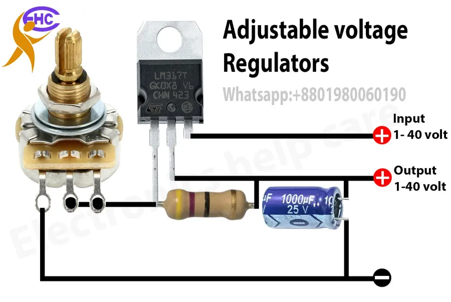
The LM317 is a versatile three-terminal adjustable positive voltage regulator capable of supplying more than 1.5A over an output range of 1.25V to 37V. Its adjustability makes it a popular choice for applications requiring custom voltage outputs.
Pin Configuration:
Typical Circuit: The output voltage is set by an external resistor divider connected between the output and the adjust pin. This allows the designer to easily set the voltage output of the regulator. The typical formula is Vout = 1.25 * (1 + R2/R1), where R1 is the resistor between the output and adjust pin and R2 is the resistor between the adjust pin and ground.
Applications: Ideal for applications such as variable power supplies, battery chargers, and precision voltage references where adjustable voltage levels are necessary. The LM317’s flexibility makes it a component of choice in many benchtop and test equipment designs.
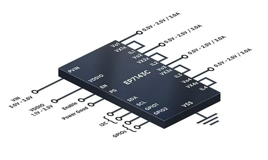
Integrated Voltage Regulators (IVRs) represent a significant advancement in power management technology, offering enhanced performance, reduced size, and improved efficiency compared to traditional discrete voltage regulators. These monolithic devices integrate the control circuitry and power stage within a single chip, enabling more compact and efficient power solutions.
IVRs utilize advanced semiconductor manufacturing processes, allowing for precise control of voltage regulation and significantly reducing parasitic inductances and capacitances. These reductions lead to faster transient response times, lower output impedance and reduced voltage ripple, improving the power delivery for highly demanding applications such as microprocessors and high-speed digital circuits.
Furthermore, the integration of IVRs can lead to a reduction in component count, simplifying circuit board design and lowering the overall system cost. The inherent reduction in size is critical for portable and wearable devices where space constraints are paramount. IVRs also offer advantages in terms of thermal management, distributing heat more evenly across the chip and potentially reducing the need for large heat sinks.
The adoption of IVR technology is driven by increasing demands for high-performance, energy-efficient power supplies across a wide range of applications, including data centers, mobile computing, and automotive electronics. As semiconductor technology continues to advance, IVRs are poised to become an increasingly essential component in modern electronic systems, displacing traditional discrete regulators.
Selecting the appropriate voltage regulator IC is crucial for ensuring stable and reliable operation of electronic circuits. This guide provides a structured approach to help you choose the right regulator based on your application requirements, encompassing key considerations and a systematic decision-making process.
This section addresses frequently asked questions concerning voltage regulator ICs, providing concise and clear answers to common queries. Understanding these answers will help you to better choose and apply voltage regulator ICs.
Voltage regulator ICs, whether the ubiquitous 7805 or more advanced Integrated Voltage Regulators, are indispensable components in modern electronics. By ensuring a stable voltage supply, they safeguard the performance and longevity of countless devices. Understanding the various types of voltage regulator ICs, their parameters, and applications empowers engineers and hobbyists to make informed design choices. As technology continues to advance, the role of these power management ICs will only become more critical, pushing the boundaries of electronic efficiency and performance.

