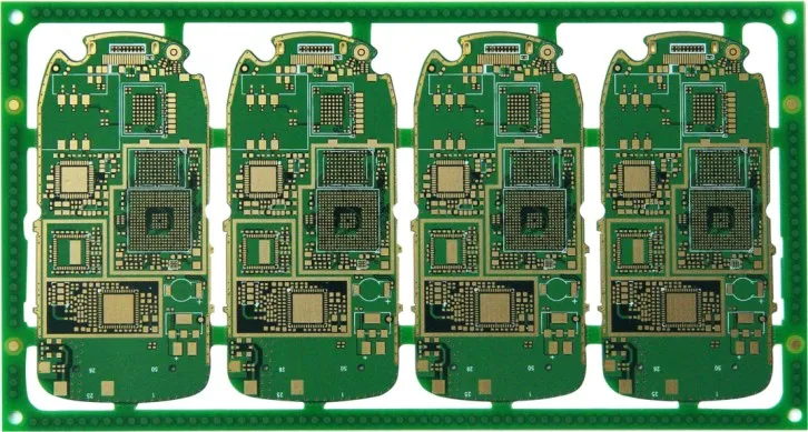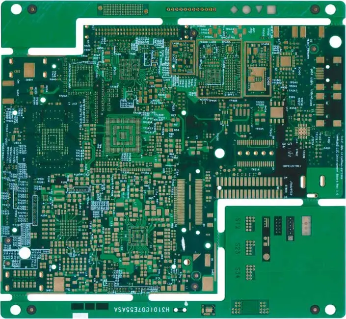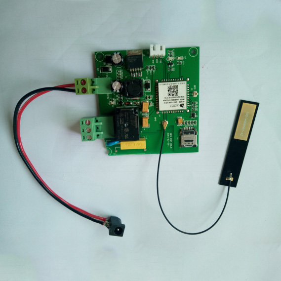
AnyPCBA PCB and PCBA case studies


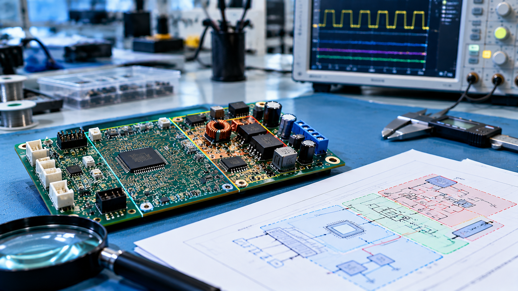
Mixed-signal embedded control boards are the core hardware for applications such as robot controllers, drone flight controllers, and industrial automation boards. These boards typically integrate MCU, sensor interfaces, high-power motor drives, and power conversion on a single PCB — placing far greater demands on layout design than standard digital boards.
The core conflict: the MCU and sensors require clean, stable power and a quiet signal environment, while the motor drive and switching power supply generate high currents and high di/dt noise. If the layout is poor, power noise can couple through ground loops, power paths, and spatial coupling — interfering with sensitive circuits, causing abnormal sensor data, MCU malfunctions, or even system failure.
AnyPCBA has extensive experience in the design and manufacturing of mixed-signal control board PCBA. This case study uses a typical "MCU + sensor + motor drive" architecture to systematically outline the key design and manufacturing considerations for functional partitioning, grounding strategy, power tree design, sensitive signal protection, and high-current path optimization.
Mixed-signal control board design faces multiple conflicting challenges:
| Challenge | Requirements | Design Difficulty |
|---|---|---|
| Noise Isolation | Power noise must not interfere with MCU and sensors | High-current loops and sensitive signals coexist on the same board |
| Grounding Strategy | Effective management of digital, analog, and power grounds | Different ground types must be separated yet connected |
| Power Integrity | Clean, stable power for each module | Power paths for power and sensitive zones must be isolated |
| Sensitive Signal Protection | Accurate transmission of motor feedback signals | Signal lines cross noise zones and are easily disturbed |
| Thermal Management | Effective heat dissipation for MOSFETs and power devices | High power density, localized heat concentration |
| EMC Performance | Meeting radiated and conducted standards | Suppression of switching noise and motor noise |
The core of mixed-signal board layout is partitioning by function and maintaining adequate spacing. Typical partitions include:
| Functional Zone | Components | Layout Guidelines |
|---|---|---|
| Digital Zone | MCU, memory, digital interfaces (USB, UART) | Centered or near interface side, away from power zone |
| Analog/Small-Signal Zone | Sensor interfaces, ADC, precision reference | Independent area, close to sensor connectors |
| High-Power/Noise Zone | Motor drivers, MOSFETs, freewheeling diodes, bulk capacitors | Close to motor connectors, away from sensitive zones |
| Power Conversion Zone | Buck/Boost converters (supplying main board and motor drive) | Close to power input, short and thick high-current paths |
Partitioning principles:
Maintain adequate spacing between zones
Use ground isolation bands for isolation
Consider physical slots when necessary (use cautiously — affects structural strength)
Grounding design is critical to mixed-signal board performance. It's essential to distinguish between digital ground (DGND), analog ground (AGND), and power ground (PGND):
| Ground Type | Coverage | Characteristics |
|---|---|---|
| Digital Ground (DGND) | MCU and surrounding digital circuits | Carries digital switching currents, higher noise |
| Analog Ground (AGND) | Sensors and signal conditioning circuits | Carries small signal currents, sensitive to noise |
| Power Ground (PGND) | Motor drive bridge, power converter high-current loops | Carries large currents, highest noise |
Connection strategy:
Connect different ground types at a single point at the power entry, or through ferrite beads / 0Ω resistors at specific points
Typically, DGND and AGND are connected (single-point connection beneath the ADC or MCU)
PGND connects separately back to the main input ground, avoiding large currents flowing through sensitive ground planes
Power distribution is another core aspect of mixed-signal board design.
Key design points:
Provide an independent, robust power input path (wide copper) for the high-power zone (motor drive), separate from digital/analog power
Use ferrite beads or π-type filters for isolation on power connections between the noise zone (motor drive) and sensitive zones (MCU, sensors)
Place decoupling capacitors close to the power pins of each functional module
Motor position feedback signals connected to the MCU (such as Hall sensor or encoder signals) are most susceptible to power noise interference.
Protection measures:
Use differential routing or shielded traces (ground shielding on PCB)
Keep these signal lines away from high-current paths and PWM control lines
Keep signal lines short and direct, avoiding crossing power zones
Motor drive phase lines and power input/output lines must carry large currents.
Optimization measures:
Use wide copper traces or multilayer copper pours to reduce resistance and inductance
Minimize voltage drop and switching noise
Avoid vias in high-current paths when possible; use multiple parallel vias when necessary
Motor drive MOSFETs and high-power resistors are the primary heat sources.
Design points:
Design large thermal pads beneath MOSFETs and high-power resistors
Connect to inner or backside copper planes through thermal via arrays
Reserve space for external heatsinks when necessary
For high power density designs, consider metal-core PCB or heavy copper PCB
| Outcome Dimension | Value Delivered |
|---|---|
| MCU Stability | Functional partitioning and grounding ensure MCU is free from power noise |
| Sensor Accuracy | Independent analog zone ensures accurate, reliable sensor data |
| Motor Drive Performance | Optimized high-current paths ensure efficient, reliable motor operation |
| EMC Performance | Meets radiated and conducted standards through partitioning, isolation, and filtering |
| Thermal Performance | Thermal pads and via arrays effectively manage power device heat |
| System Robustness | Modules work together with high overall system robustness |
Robot controllers
Drone flight controllers
Industrial automation control boards
Motor drive and motion control
Smart actuators and servo systems
Embedded power electronics
This project demonstrates AnyPCBA's core capabilities in mixed-signal control board PCBA design and manufacturing:
✅ Functional partitioning — digital, analog, and power zones clearly divided, noise isolated
✅ Grounding strategy — DGND, AGND, PGND separated with single-point connection
✅ Power tree design — independent power paths, ferrite bead / π-filter isolation
✅ Sensitive signal protection — differential routing, ground shielding, away from noise sources
✅ High-current path optimization — wide copper, multilayer pours, reduced voltage drop and inductance
✅ Thermal management — thermal pads, via arrays, heatsink reservation
✅ Prototype to production — supporting small-batch to medium-volume production
Need Mixed-Signal Control Board PCBA Design and Manufacturing Support?
AnyPCBA has extensive experience in mixed-signal control boards, covering robot controllers, drone flight controllers, and industrial automation boards. Our manufacturing capabilities cover 2-64 layers, including HDI, rigid-flex, heavy copper, and high-frequency hybrid processes. Our engineering team provides DFM/DFA design reviews before production to help identify potential issues in functional partitioning, grounding strategy, power tree design, and thermal management.
Contact us to discuss your project →