Imagine the smooth, unwavering power delivery in your electric car or the consistent output of a solar inverter. At the heart of these seamless operations lies a seemingly simple component: the DC link capacitor. This often-overlooked device acts as a critical intermediary, smoothing out fluctuations and ensuring a stable flow of energy in countless modern applications. This article delves deep into the world of DC link capacitors, exploring their functionality, design, selection criteria, and the critical role they play in shaping our electrified world.
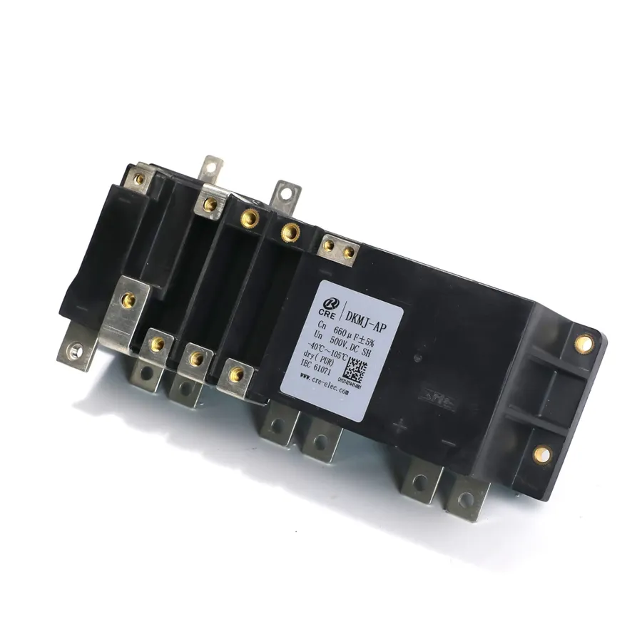
DC link capacitors are fundamental components in power electronic circuits, acting as energy reservoirs that stabilize DC voltage levels between the rectifier and inverter stages. Their primary function is to minimize voltage ripple and provide a consistent power supply, thereby ensuring efficient operation and preventing damage to sensitive electronics. These capacitors store energy during periods of high supply voltage and release it during voltage sags, effectively smoothing the DC bus voltage.
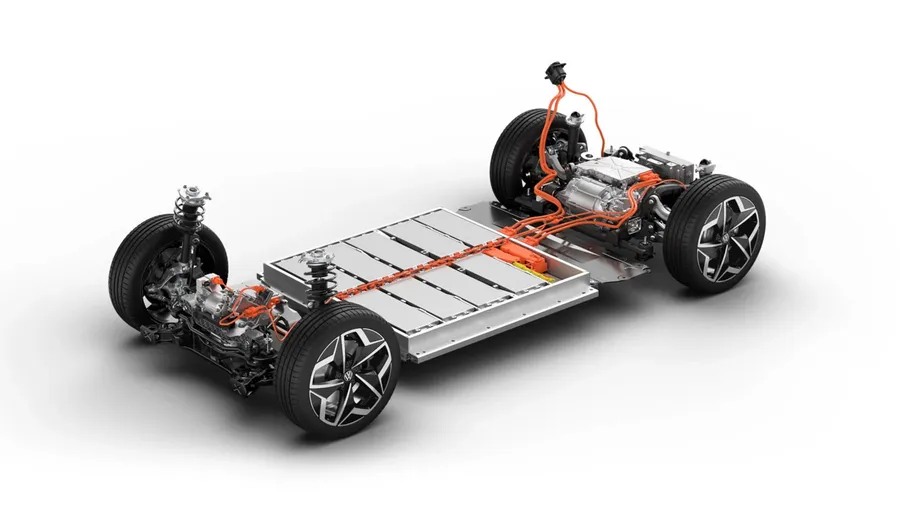
In electric vehicles (EVs), DC link capacitors are indispensable components, serving as a crucial intermediary for managing power flow between the battery, the inverter, and the electric motor. Their primary function is to stabilize the DC voltage, ensuring efficient and reliable performance of the electric drive system. These capacitors are also essential in managing regenerative braking, capturing energy during deceleration and feeding it back into the battery.
The role of DC link capacitors in EVs is multifaceted:
| Application | Function | Benefit |
|---|---|---|
| Normal Operation | Provides stable DC voltage to the motor inverter. | Ensures smooth and efficient motor operation. |
| Acceleration | Buffers energy to meet peak power demands. | Enhances vehicle performance by providing immediate energy for rapid acceleration. |
| Regenerative Braking | Captures and manages energy feedback. | Improves overall energy efficiency by reusing deceleration energy and reducing energy waste. |
The performance and reliability of an EV’s powertrain system is directly dependent on the quality and characteristics of the DC link capacitors. Therefore, careful selection and design considerations are essential for optimal EV performance and long-term reliability.
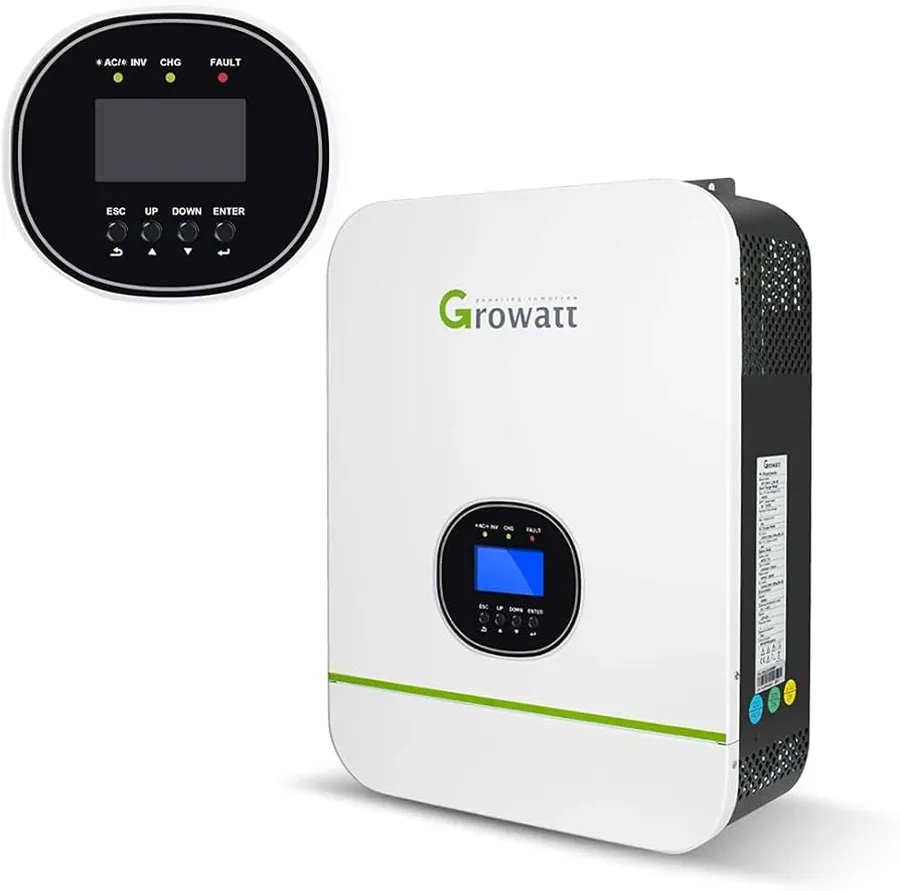
DC link capacitors are indispensable components within renewable energy systems, functioning as vital intermediaries that ensure voltage stability and facilitate efficient power conversion, ultimately enabling seamless integration with the electrical grid. These capacitors are crucial in managing the fluctuating power output from renewable sources like wind and solar, maintaining a stable DC voltage for downstream inverters and power conversion equipment.
In wind energy systems, DC link capacitors mitigate voltage variations caused by the intermittent nature of wind power, smoothing out the power supplied to the grid. Similarly, in solar photovoltaic (PV) systems, these capacitors stabilize the DC voltage output from solar panels before it's inverted into AC power for distribution.
The effective management of voltage and current by DC link capacitors is pivotal in preventing grid instability and ensuring the consistent and reliable delivery of renewable energy. Their role is paramount in achieving optimal energy conversion efficiency and enhancing the long-term performance of renewable energy installations.
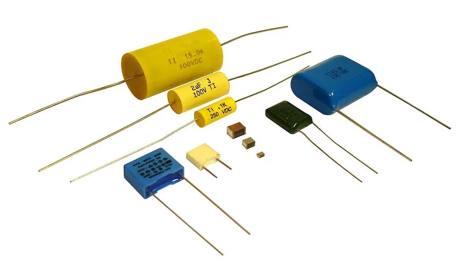
DC link capacitors are crucial components in power electronics, and their performance is heavily influenced by the type of capacitor technology employed. This section provides a detailed comparison of film, electrolytic, and multilayer ceramic (MLCC) capacitors, highlighting their unique characteristics, advantages, disadvantages, and suitability for various DC link applications.
| Feature | Film Capacitors | Aluminum Electrolytic Capacitors | MLCC (Multilayer Ceramic Capacitors) |
|---|---|---|---|
| Reliability | High, long lifespan | Moderate, can degrade over time | High, very robust |
| Capacitance | Moderate, lower than electrolytics | High, good for bulk capacitance | Low to moderate |
| Size | Moderate to large | Moderate to large | Small, compact |
| ESR (Equivalent Series Resistance) | Low | Moderate to high | Very Low |
| Temperature Range | Wide | Limited | Wide |
| Cost | Moderate to High | Low to Moderate | Moderate |
| Applications | High reliability systems, inverters, EV | Bulk energy storage, general purpose | High frequency circuits, compact designs |
| Advantages | High reliability, low ESR, good temperature stability | High capacitance, cost-effective for bulk storage | Small size, low ESR, good high-frequency performance |
| Disadvantages | Larger size for similar capacitance, Higher cost | Limited lifespan, temperature sensitive, Higher ESR | Limited capacitance compared to electrolytics, can exhibit capacitance variation with voltage |
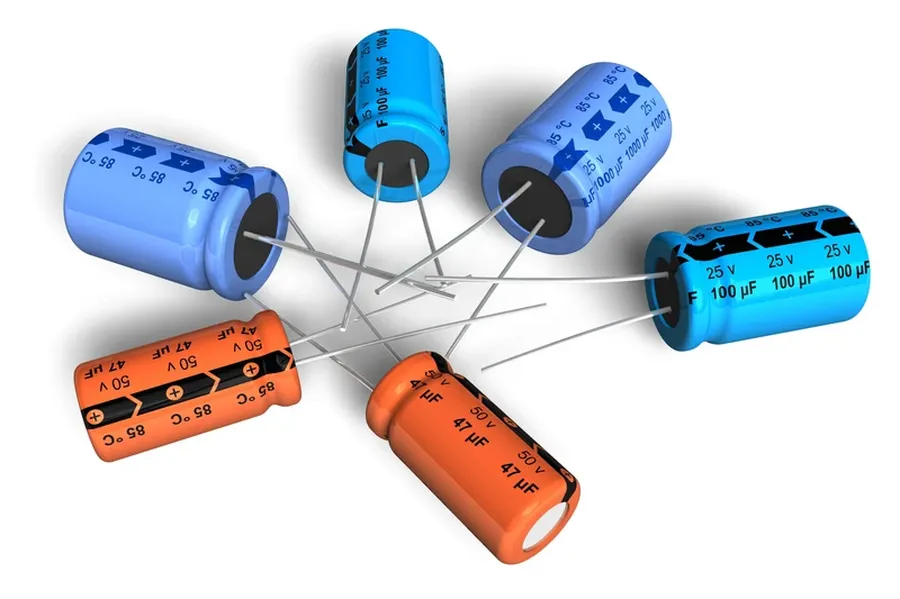
Selecting the appropriate DC link capacitor is crucial for the reliable and efficient operation of power electronic systems. This process involves carefully considering several key parameters to ensure the capacitor meets the specific demands of the application. These parameters include voltage rating, capacitance value, current handling capability, temperature characteristics, and physical size, each contributing uniquely to the overall performance and longevity of the system.
| Parameter | Description | Importance |
|---|---|---|
| Voltage Rating | The maximum DC voltage the capacitor can withstand continuously without failure. | Essential to prevent dielectric breakdown and ensure safe operation. The capacitor's voltage rating must exceed the expected maximum system voltage. |
| Capacitance Value | The amount of charge the capacitor can store at a given voltage. | Determines the energy storage capacity and ripple voltage characteristics. The value affects the system's ability to buffer voltage fluctuations. |
| Current Handling Capability | The maximum current (RMS and peak) the capacitor can safely handle without overheating or damage. | Critical for preventing thermal runaway and ensuring the longevity of the capacitor. The capacitor must be able to handle the expected current within the system. |
| Temperature Characteristics | The capacitor’s performance variations across its operating temperature range. | Affects capacitance, ESR (Equivalent Series Resistance), and lifespan. It is vital to select a capacitor with suitable temperature performance for its environment. |
| Physical Size | The dimensions and form factor of the capacitor. | Important for integrating into the application, space limitations, and compatibility with the physical enclosure or mounting requirements. |
Matching the capacitor specifications to the application requirements is crucial for optimal performance and reliability. It involves a thorough analysis of the system’s voltage, current, and temperature profiles to ensure the chosen capacitor meets the operational demands, maintains performance within the operational environment, and complies with size constraints. This rigorous approach is vital to avoiding premature failure and ensuring the efficient operation of the DC link in your power electronics system.
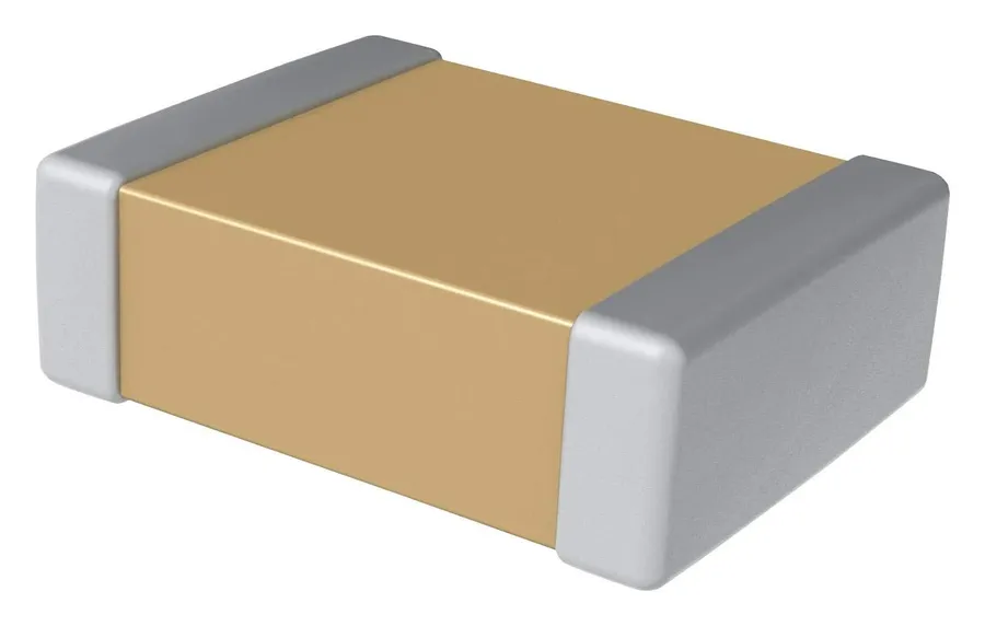
Designing a system incorporating DC link capacitors requires a holistic approach, addressing not only the capacitor selection but also the broader circuit environment. This includes careful consideration of circuit layout, thermal management, and protective measures to ensure the capacitor's reliability and the system's overall performance.
Proper PCB design, effective heat dissipation, and implementation of robust protection strategies are crucial for optimal DC link capacitor performance. Neglecting these aspects can lead to premature capacitor failure, system instability, and compromised reliability.
| Design Aspect | Considerations | Implications |
|---|---|---|
| PCB Layout | Short, wide traces, minimize parasitic inductance, close proximity to power devices | Reduced impedance, improved current handling, minimized voltage drop |
| Thermal Management | Heat sinks, forced air cooling, strategic component placement, thermal vias | Extended capacitor lifespan, stable performance, prevention of premature failure |
| Protection Measures | TVS diodes, fuses, overcurrent and overvoltage protection circuits | Protection against transient events, prevention of capacitor damage, improved system reliability |
This section addresses common queries about DC link capacitors, providing clear and concise answers to enhance understanding of their function and application.
Determining the correct capacitance for DC link capacitors in 3-phase inverters is crucial for ensuring stable and efficient operation. The capacitor acts as a buffer, smoothing out voltage ripples caused by switching actions and load variations. Proper calculation and selection of this capacitance are essential for optimizing inverter performance and longevity, minimizing harmonic distortion and preventing premature failure.
The calculation of the DC link capacitance involves several critical factors, primarily related to the ripple current and the permissible voltage ripple. These are outlined as follows:
A simplified formula can be used as a starting point for capacitance calculation. However, this formula often needs adjustment based on specific conditions and is based on the first principle of the charge-discharge cycle of the capacitor.
C = \frac{I_{ripple}}{2 \cdot f_{sw} \cdot \Delta V}
Where:
It's important to note that this simplified formula provides a starting estimate. In practice, more comprehensive analysis and simulations, especially with Finite Element Analysis (FEA), may be needed. The effective capacitance under operating conditions can be affected by various factors such as temperature and frequency, thus requiring adjustments to the calculated value. Additionally, derating factors for voltage, current, and temperature should be applied based on the capacitor manufacturer's specifications to ensure reliable operation.
| Parameter | Description | Impact on Calculation |
|---|---|---|
| Ripple Current | AC current component through the capacitor due to switching | Directly influences the required capacitance value; higher ripple current requires larger capacitance |
| Voltage Ripple | Permissible variation in DC link voltage | Determines the stability of the system; tighter voltage ripple requirements necessitate higher capacitance |
| Switching Frequency | Rate at which inverter switches operate | Higher switching frequency leads to smaller capacitance; but also increases switching losses and EMI. |
| DC Bus Voltage | Nominal DC voltage level in the inverter | Sets capacitor voltage rating |
| Load Characteristics | Type and current demands of the load driven by the inverter | Dictates the amount of charge/discharge current, influencing capacitance requirements |
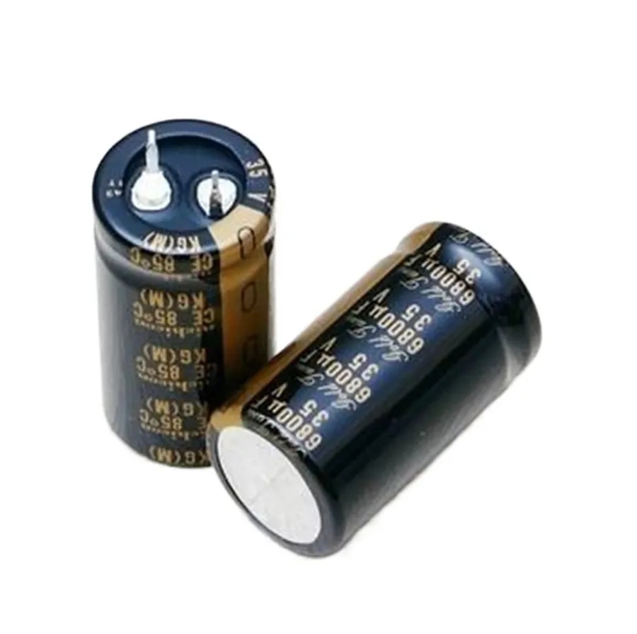
The field of DC link capacitor technology is undergoing rapid evolution, driven by the increasing demands for higher performance, smaller size, and extended lifespan in modern power electronics. This section explores emerging trends in material science, capacitor design, and integration methods that are shaping the future of these critical components.
DC link capacitors are the unsung heroes of modern power electronics, quietly ensuring the stable and efficient operation of a multitude of devices, from electric vehicles to renewable energy systems. Understanding their role, types, and selection criteria is crucial for engineers and designers looking to create reliable and high-performing electrical systems. As technology advances, DC link capacitors will continue to evolve, playing an ever-increasingly vital role in a more electrified world, pushing the boundaries of what's possible in energy storage and power conversion.

