The Arduino Micro, a compact yet powerful microcontroller board, opens up a world of possibilities for electronics enthusiasts and professionals alike. Understanding its pin layout is paramount for successful project development. This guide delves into the intricacies of the Arduino Micro pin layout, explaining each pin's function and how to utilize them effectively in your designs. From digital I/O to analog inputs and PWM outputs, we will demystify the seemingly complex world of pin configurations so that you can easily navigate your next electronics project.
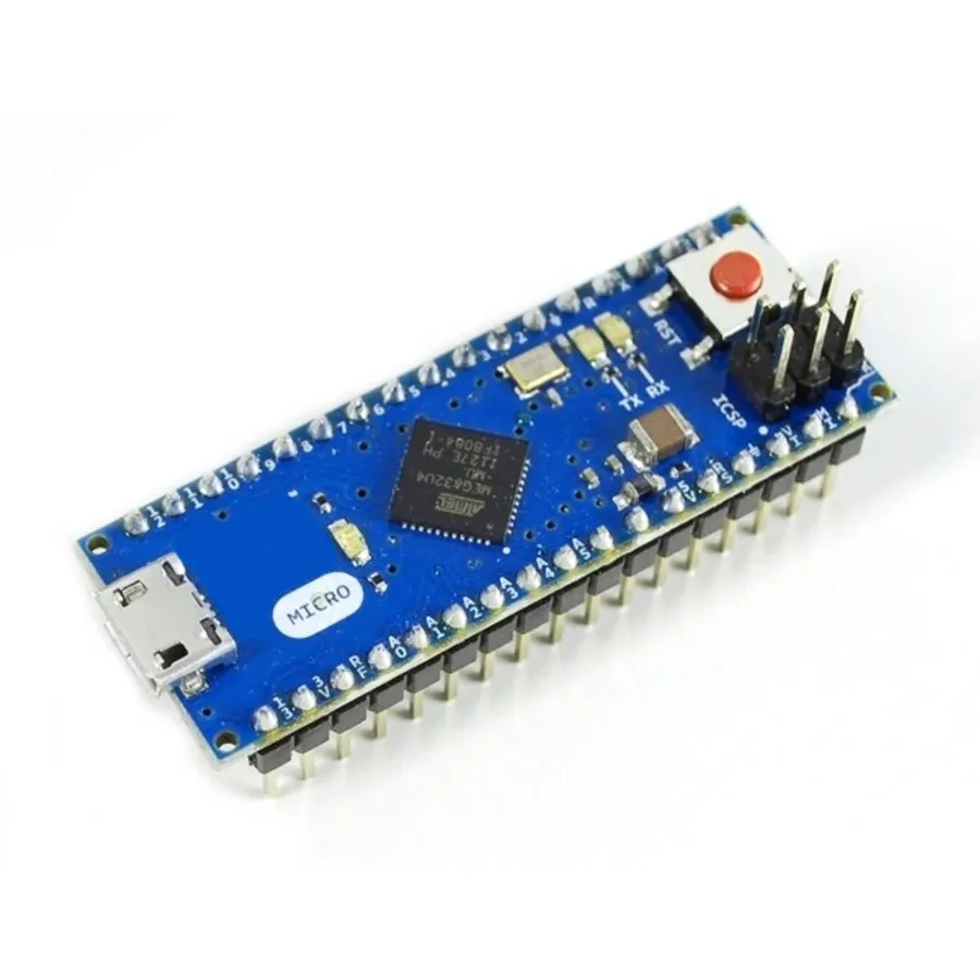
The Arduino Micro's functionality hinges on its versatile pin configuration, with 20 digital input/output pins forming the core of its interaction with the physical world. Each pin's dual nature, configurable as either an input or output, provides immense flexibility. Moreover, several of these pins possess additional capabilities like acting as Pulse Width Modulation (PWM) outputs for precise control or Analog-to-Digital Converter (ADC) inputs for sensor data acquisition.
| Pin Type | Number of Pins | Primary Function | Secondary Functions |
|---|---|---|---|
| Digital I/O | 20 | General-purpose input or output | PWM, Analog Input |
| Analog Input | 12 | Analog signal measurement | Digital I/O |
| PWM Output | 7 | Variable signal output | Digital I/O |
| Power | 3 | Power supply and grounding | N/A |
| Communication | Multiple | Data transmission and receiving | Digital I/O |
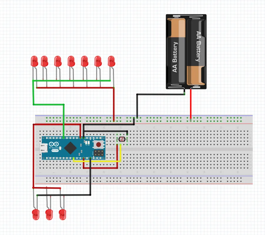
The Arduino Micro boasts 20 digital input/output (I/O) pins, designated by numbers 0 to 19. These pins are the fundamental building blocks for interfacing the microcontroller with external electronic components, sensors, and other devices. Each pin can be independently configured as either an input or an output, offering great versatility.
When configured as an output, these pins can supply a digital signal, which is either high (typically 5V) or low (0V), allowing for control of external components. When configured as an input, the pins can read the digital state of external sensors or switches and report them to the microcontroller. The direction (input or output) is defined within the Arduino code using functions like `pinMode()`.
| Feature | Description |
|---|---|
| Total Number | 20 (Numbered 0 to 19) |
| Functionality | Configurable as either input or output |
| Output Voltage | Typically 5V (High) or 0V (Low) |
| Input Voltage | Reads digital HIGH (above 3V) or LOW (below 1.5V) |
| Current Capacity | Capable of sourcing or sinking a limited amount of current |
While the primary function of these pins is digital I/O, some also offer secondary functionalities, such as Pulse Width Modulation (PWM) or Serial Communication. Proper understanding of these dual-use capabilities is crucial for maximizing the capabilities of the Arduino Micro.
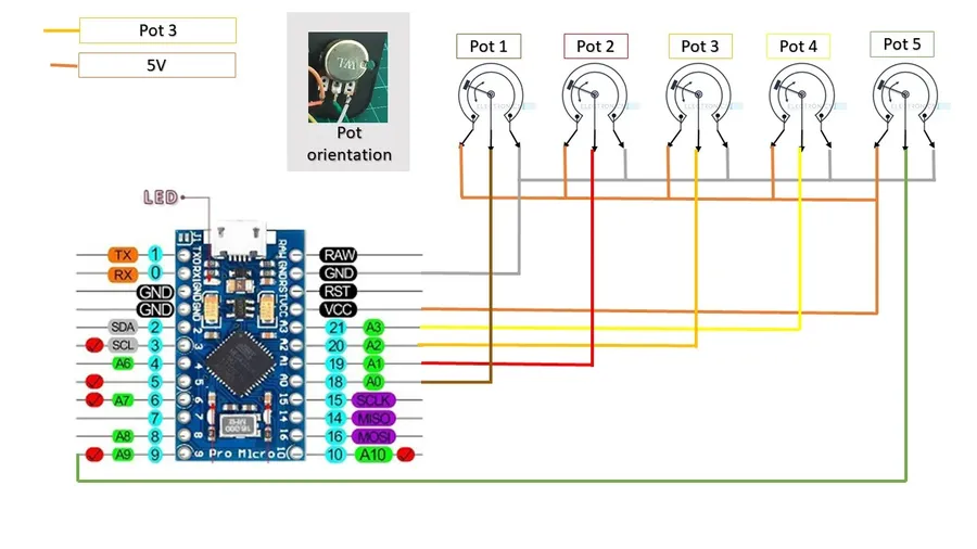
The Arduino Micro is equipped with 12 analog input pins, labeled A0 through A11, which facilitate the interaction with real-world analog signals. These pins serve as the interface for sensors and other analog devices by converting continuous analog signals into digital values that the microcontroller can process. This conversion is critical for applications that measure parameters such as temperature, light, or pressure. Understanding this process is paramount to harnessing the full potential of the Arduino Micro's interaction with its environment.
Each of the 12 analog pins is connected to an internal Analog-to-Digital Converter (ADC). The ADC has a 10-bit resolution, meaning it can convert analog voltages into digital values ranging from 0 to 1023. By default, the ADC reference voltage is set to 5V, resulting in a step size of approximately 4.9 mV per digital value (5V / 1024).
| Feature | Description |
|---|---|
| Pin Range | A0 to A11 |
| Number of Analog Pins | 12 |
| ADC Resolution | 10-bit |
| Digital Value Range | 0 to 1023 |
| Default Reference Voltage | 5V |
| Step Size | Approximately 4.9 mV per digital value |
Interpreting analog readings involves understanding that each digital value read corresponds to a specific voltage level. For instance, a reading of 0 means the analog pin is at 0V, while a reading of 1023 indicates a voltage near the reference voltage (nominally 5V). Values in between correlate proportionally. To obtain precise readings, consider that external factors and sensor characteristics may introduce inaccuracies or offset. In many applications, calibration of the sensor reading and environmental compensation are required to obtain accurate measurement.
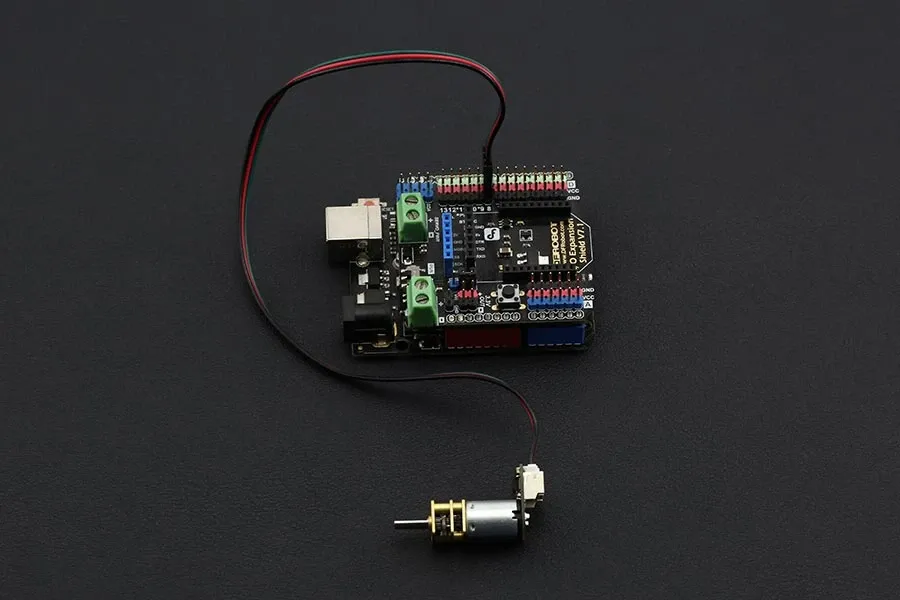
The Arduino Micro incorporates 7 Pulse Width Modulation (PWM) pins, crucial for applications requiring variable signal control. These pins, denoted by a tilde (~), enable the generation of analog-like outputs from digital signals, making them essential for motor speed regulation, LED brightness control, and servo motor positioning. The underlying principle of PWM involves modulating the width of a pulse at a fixed frequency to control the average power delivered to a load.
| Pin Number | Function | Description | Typical Application |
|---|---|---|---|
| Digital Pin 3 (~) | PWM Output | General purpose PWM pin. | LED brightness control. |
| Digital Pin 5 (~) | PWM Output | General purpose PWM pin. | DC motor speed control. |
| Digital Pin 6 (~) | PWM Output | General purpose PWM pin. | Servo motor control. |
| Digital Pin 9 (~) | PWM Output | General purpose PWM pin. | Analog-like volume control. |
| Digital Pin 10 (~) | PWM Output | General purpose PWM pin. | Backlight dimming. |
| Digital Pin 11 (~) | PWM Output | General purpose PWM pin. | Generating audio signals. |
| Digital Pin 13 (~) | PWM Output | General purpose PWM pin. | Color mixing in RGB LEDs |
The Arduino Micro's PWM functionality operates at a frequency of approximately 490 Hz for most pins. The `analogWrite()` function is used to specify the duty cycle, ranging from 0 (always off) to 255 (always on). This value represents the proportion of the cycle for which the pin is HIGH. For instance, an `analogWrite(pin, 127)` will result in a pulse that is HIGH for approximately 50% of the time, creating an average voltage halfway between 0V and 5V.
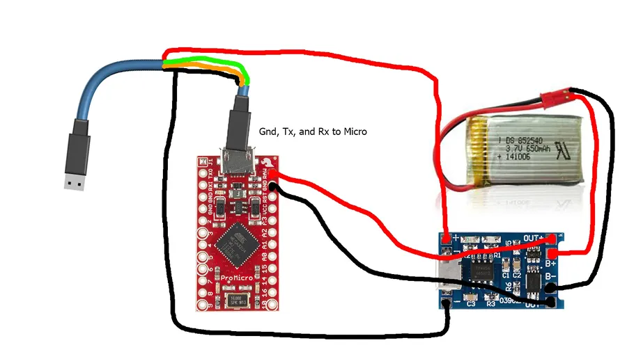
The Arduino Micro requires a stable power supply to operate correctly. Understanding its power pins is crucial for ensuring reliable performance. This section details the VCC, GND, and RAW pins, and discusses how to provide power to the Micro using various methods.
| Pin Name | Description | Voltage Level | Functionality |
|---|---|---|---|
| VCC | Positive supply voltage pin. | 5V | Connects to the regulated 5V power supply to power the microcontroller and peripherals. |
| GND | Ground or 0V reference pin. | 0V | Connects to the ground terminal of your power source. |
| RAW | Unregulated power input pin, typically accepts 7-12V. | 7-12V | Connects to the positive terminal of an unregulated power supply. The on-board regulator reduces the voltage to 5V. Note: This pin bypasses the USB power source and is not recommend to be lower than 7V. |
The Arduino Micro can be powered via the USB connection or an external power supply. When using USB, the board receives a regulated 5V directly. For external power, it is recommended to use a power supply that falls in the range of 7 to 12 volts to account for the onboard voltage regulator’s overhead. Ensure that the power supply's current rating is adequate for your application.
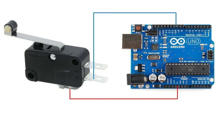
The Arduino Micro utilizes several communication protocols to interface with external devices and sensors. These protocols—UART (Serial), SPI, and I2C (also known as TWI)—each have specific pin assignments crucial for establishing reliable communication. Understanding these pin configurations is vital for seamless integration with other hardware components.
| Communication Protocol | Pin Name(s) | Function | Description |
|---|---|---|---|
| UART (Serial) | TX, RX | Transmitter, Receiver | Asynchronous serial communication; used for sending and receiving data. |
| SPI | MISO, MOSI, SCK, SS | Master In Slave Out, Master Out Slave In, Serial Clock, Slave Select | Synchronous serial communication; used for high-speed data transfer. |
| I2C (TWI) | SDA, SCL | Serial Data, Serial Clock | Two-wire serial communication; used for communication between multiple devices. |
On the Arduino Micro, the specific pins used for each protocol are as follows: * **UART:** The TX pin (digital pin 1) is used for transmitting serial data, and the RX pin (digital pin 0) is used for receiving serial data. These pins facilitate asynchronous serial communication, often used for sending text-based data to and from a computer or other serial devices. * **SPI:** The SPI communication pins are located on digital pins 14 (MISO), 16 (MOSI), and 15 (SCK). The SS (Slave Select) pin may vary depending on usage but is typically digital pin 10. SPI is primarily used for high-speed, synchronous data transfer, such as communication with sensors, displays and memory modules. * **I2C (TWI):** The I2C communication pins are located on analog input pins A4 (SDA) and A5 (SCL). The SDA pin carries data, while the SCL pin provides the clock signal. I2C is typically used for communication with multiple sensors or peripheral devices. Note that the I2C pins share functionality with analog input pins A4 and A5.
The Arduino Micro pinout diagram serves as an essential visual reference for understanding the physical location and function of each pin on the board. This diagram is crucial for correctly connecting components, sensors, and other peripherals to the Arduino Micro, ensuring proper functionality and avoiding potential damage.
A comprehensive pinout diagram typically includes the following information:
While a visual diagram is crucial for pin identification, always cross-reference with the official Arduino Micro datasheet for precise specifications, voltage levels and current limitations.
Below is a typical representation of the Arduino Micro pin layout, the physical representation and pin numbering may vary slightly based on the specific manufacturer and version of the board.
It is recommended to always have access to the official pinout diagram PDF for accurate information, as many online sources can contain outdated or inaccurate layouts. The most reliable source for this information is the Arduino official website documentation for the Arduino Micro board.
This section addresses common inquiries regarding the Arduino Micro pin layout, providing concise and accurate answers to help users effectively utilize this compact microcontroller.
Understanding the Arduino Micro pin layout, with its diverse array of digital, analog, and PWM capabilities, is crucial for leveraging its full potential. The Arduino Micro pin layout is more compact than its larger counterparts, yet it provides similar functionality, making it ideal for space-constrained applications. Mastery of the pinout enables precise control over electronic projects, paving the way for innovation in the ever-evolving world of embedded systems. Whether you're a beginner or an experienced maker, familiarity with the Arduino Micro pin layout empowers you to build more effective and sophisticated electronic solutions.

