Understanding IC Logic Gates: A Comprehensive Guide
2025.01.30
In our daily lives, hidden behind the smooth facade of our electronic gadgets, lies a complex network of tiny switches – IC logic gates. These fundamental building blocks of digital circuits, akin to the neurons in our brains, use the simple logic of 0s and 1s to execute everything from turning on a light to complex calculations. In this article, we'll explore the fascinating realm of IC logic gates, delving into their types, functions, and applications, providing a comprehensive understanding of these ubiquitous components.
What are IC Logic Gates?
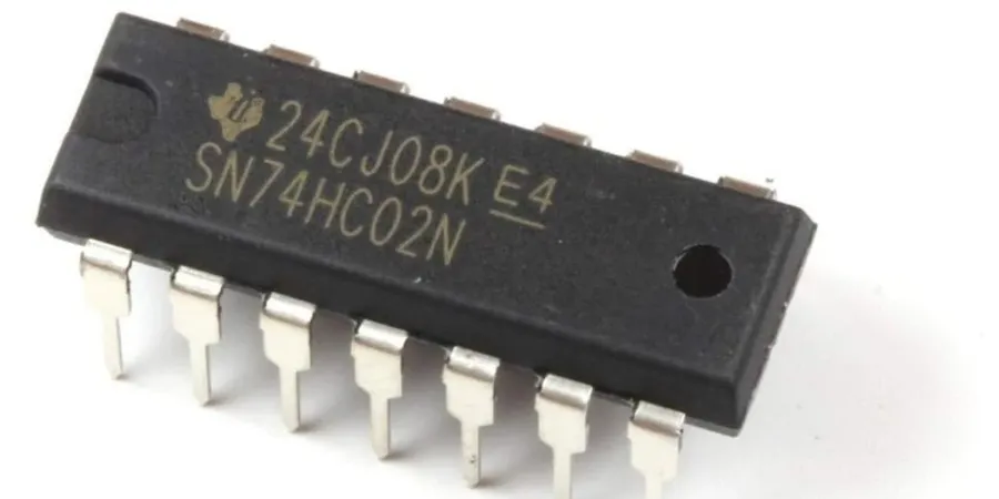
IC Logic Gate Chip
Integrated Circuit (IC) logic gates are the fundamental building blocks of digital circuits. These miniature electronic components perform logical operations on binary inputs (0s and 1s), acting as electronic switches governed by Boolean algebra to create complex digital systems. Their role in modern electronics cannot be overstated; they are the core of digital processing.
Basic Types of IC Logic Gates
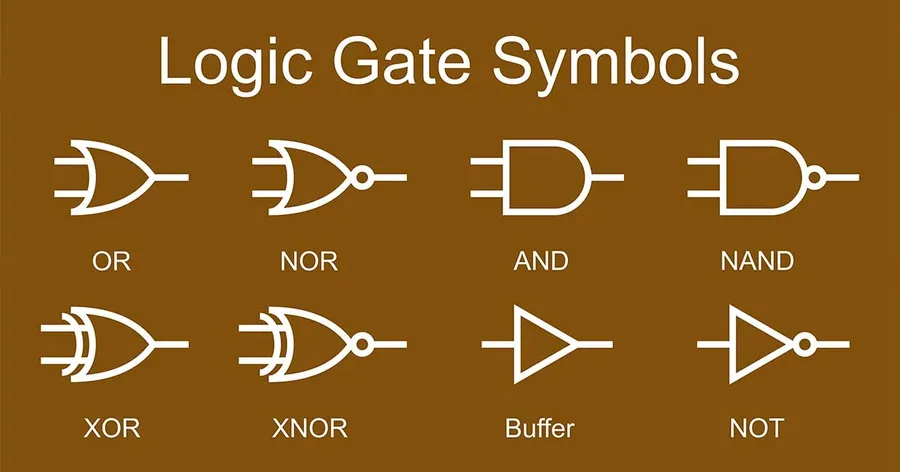
Logic Gate Symbols
Integrated circuit (IC) logic gates are the fundamental building blocks of digital circuits. They perform logical operations on binary inputs, and these operations form the basis for complex digital systems. This section details the six core logic gates, describing their functionality using truth tables and highlighting their unique characteristics.
The output is 1 when inputs A and B are different, and 0 when they are the same.
Each of these gates has a unique function, and they can be combined to create complex circuits that perform a wide variety of digital operations. The truth tables provided clearly define their input-output relationships, which are essential in circuit design and analysis.
Common IC Logic Gate Packages
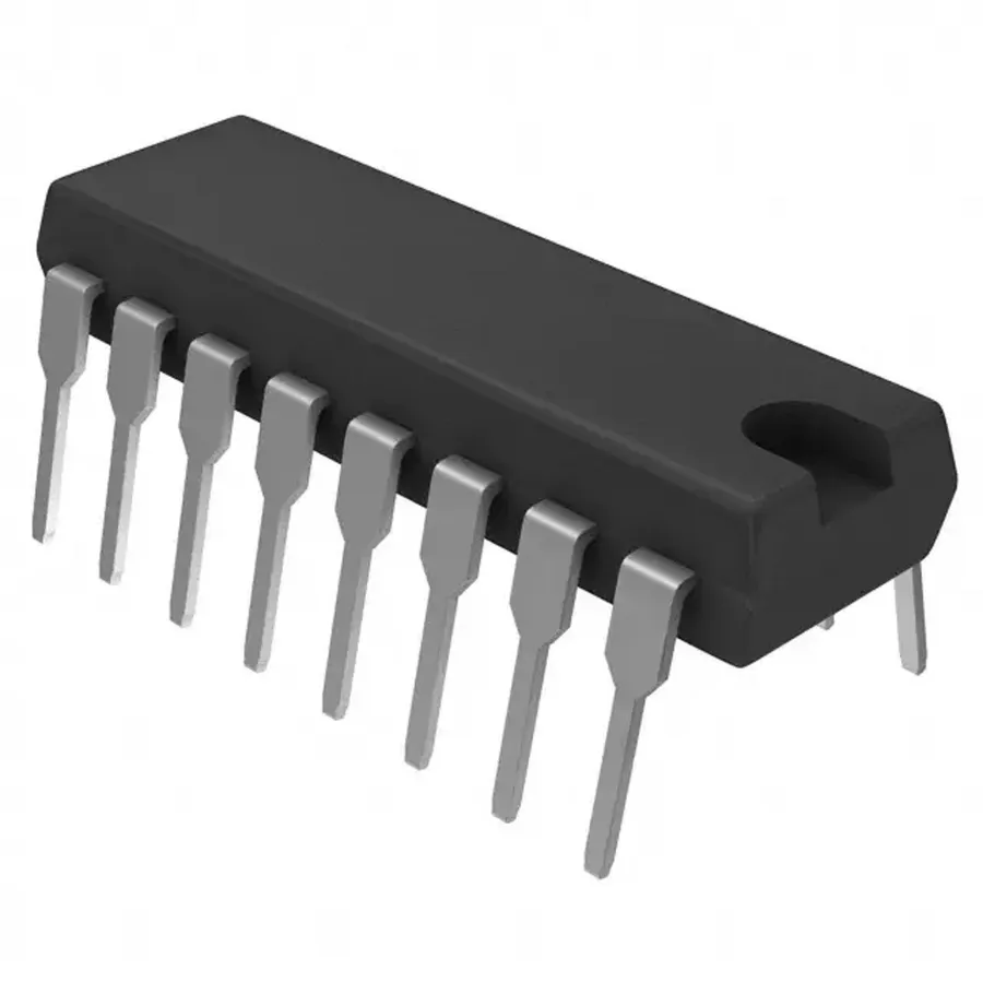
DIP Package IC
Integrated circuit (IC) logic gates are typically housed in standardized packages that facilitate their integration into electronic circuits. These packages not only protect the delicate silicon die within but also provide a convenient means of connecting the logic gates to the external circuit. Understanding the common IC packages and their characteristics is vital for efficient circuit design and implementation.
Package Type
Description
Typical Gate Count
Mounting Method
Advantages
Disadvantages
Dual Inline Package (DIP)
A through-hole package with pins extending from two sides. It is often used for prototyping and breadboarding.
4-6 gates per package depending on function and complexity.
Through-hole
Easy to prototype, good for breadboarding.
Larger size, less suitable for high-density designs.
Small Outline Integrated Circuit (SOIC)
A surface-mount package with pins extending from the sides of the package. Compact design for surface mount assembly.
Usually the same as a DIP package.
Surface mount
Smaller than DIP, suitable for high-density boards.
Difficult to handle and prototype manually.
Thin Shrink Small Outline Package (TSSOP)
A thinner version of SOIC with very fine pitch spacing of pins, allowing for more compact layouts.
Usually the same as a DIP package.
Surface mount
Very compact, good for high-density designs
Very difficult for manual prototyping, requires specialized tools and handling
Quad Flat Package (QFP)
Surface mount package with pins on all four sides, allowing for a higher number of pins. Often used with complex ICs.
Variable, may include multiple logic functions and support higher gate counts.
Surface mount
Supports higher gate density and higher pin count.
Difficult to manually prototype, requires specialized tools
The choice of package depends on factors such as the complexity of the circuit, size constraints, required mounting technique, and whether the design is intended for prototyping or mass production. Through-hole packages like DIPs are preferred for ease of prototyping and debugging, whereas surface-mount packages are widely used in commercial devices due to their compact size and suitability for automated assembly.
How IC Logic Gates Work: Inside the Chip
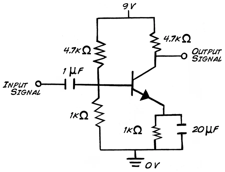
Transistor Circuit
Integrated circuit (IC) logic gates are constructed from interconnected transistors, which act as electronic switches. These transistors, typically either Bipolar Junction Transistors (BJTs) or Metal-Oxide-Semiconductor Field-Effect Transistors (MOSFETs), are arranged within the IC to perform specific Boolean logic functions, such as AND, OR, NOT, NAND, NOR, and XOR.
The fundamental principle behind logic gate operation involves using transistors to control the flow of electrical current based on the input signals. For example, in a simple AND gate, current only flows when all input transistors are activated, which results in a high output; otherwise, the output is low. The configurations of these transistors directly determine the logic operation performed by the gate.
TTL and CMOS are two primary technologies for implementing logic gates. TTL, based on BJTs, offers moderate speed but consumes more power. CMOS, utilizing MOSFETs, provides lower power consumption and higher speed. The choice between TTL and CMOS depends on the specific application requirements, including power constraints, speed requirements, and noise environment.
Applications of IC Logic Gates
Electronic Circuit Board
Integrated circuit (IC) logic gates are the fundamental building blocks of digital electronics, serving as the core components in a wide array of circuits that underpin modern technology. Their ability to perform logical operations on binary inputs allows for the creation of complex digital systems.
Timers and Oscillators Logic gates, particularly NAND and NOR gates, are fundamental in constructing astable multivibrators and other timing circuits. These circuits produce the periodic waveforms required for clock signals in digital systems.
Counters By combining flip-flops (constructed from logic gates) in a specific configuration, sequential counters are created, capable of keeping track of digital events and generating desired patterns.
Latches and Flip-Flops Logic gates are essential in the design of memory elements like latches and flip-flops, which can store a single bit of information. These are critical for sequential logic circuits and memory units.
Shift Registers Shift registers, built with flip-flops, use logic gates to provide the control signals required to shift data between memory locations, performing serial-to-parallel or parallel-to-serial data conversion.
Multiplexers and Demultiplexers Logic gates such as AND and OR gates are essential in building multiplexers (MUX) that select and route one input signal to a single output, and demultiplexers (DEMUX) that route one input signal to multiple outputs. These are crucial in data routing.
Arithmetic Logic Units (ALUs) The core of a computer's central processing unit (CPU), the ALU performs all arithmetic and logical operations. Logic gates like AND, OR, XOR, and NOT are used to construct the adders, subtractors, and other essential functions within an ALU.
These applications illustrate how logic gates are not just theoretical concepts, but are tangible electronic components that are critical to everyday technology. Their presence, often unseen, enables our modern digital world. From the simplest digital watches to the most advanced supercomputers, IC logic gates are the bedrock of digital circuits, enabling complex functionalities and are used in a variety of systems including computers, smartphones, industrial equipment, and control systems.
Selecting the Right IC Logic Gate
Selecting the appropriate IC logic gate for a specific application requires careful consideration of several key parameters. These parameters ensure that the selected gate will operate reliably within the system and will not be a limiting factor in your design. This section outlines the critical factors and provides guidance on how to interpret the specifications provided in IC datasheets.
Key factors in choosing an IC logic gate include the following:
Input Voltage Ranges Ensure that the logic gate's input voltage requirements are compatible with the voltage levels in your circuit. Mismatches can cause improper switching or damage to the gate.
Output Current Capabilities Verify the gate can source or sink sufficient current to drive the subsequent stages of your circuit or any connected loads. Insufficient current can lead to signal degradation and incorrect operation.
Speed (Propagation Delay) Consider the gate's switching speed, which is characterized by propagation delay. This delay can be a critical parameter in high-speed applications where minimizing delays is vital.
Power Consumption Evaluate the power consumption, especially for battery-powered or high-density applications where minimizing heat generation and maximizing battery life are important.
Operating Temperatures Confirm that the gate can operate reliably within the expected temperature range. Temperature variations can affect performance and reliability.
IC datasheets provide all the necessary information for selecting the right logic gate. Key parameters to look for include:
Propagation Delay The time it takes for the output to respond to a change in the input. Shorter propagation delay is better for faster operation, but can sometimes imply higher power consumption.
Fan-out The number of similar gates that the output can drive reliably. The fan-out must match the load requirements of your circuit.
Noise Margin The amount of noise that can be tolerated at the input before causing an incorrect output. A larger noise margin provides a more robust design.
Practical tips when selecting an IC logic gate:
Start with a functional requirement: Begin by understanding the specific logic function you need and select appropriate gate type based on it (e.g., AND, OR, XOR).
Check the voltage levels and loading: Review your power supply and ensure compatibility, considering input and output voltage, current needs of both the logic gate and the devices it connects to.
Review datasheet parameters Consult the datasheet carefully to identify optimal operating conditions, taking special attention to propagation delays, power requirements and noise margins.
Consider environmental conditions Make sure that the gate can operate reliably in the temperature range in your application, as specified by the operating temperature.
Compare and evaluate gate technologies Compare different logic families like TTL and CMOS, evaluating their trade-offs regarding speed, power consumption, and noise immunity to make the best selection.
Frequently Asked Questions About IC Logic Gates
This section addresses common queries regarding IC logic gates, providing clear and concise answers to help clarify any confusion. We delve into the core concepts and practical aspects of these fundamental components.
What is an Integrated Circuit (IC) in the context of logic gates? In the realm of logic gates, an Integrated Circuit (IC) refers to a miniaturized electronic circuit fabricated on a small semiconductor material chip, typically silicon. It houses multiple logic gates within a single package, providing a compact and efficient way to implement complex digital logic functions. This integration reduces size, cost, and power consumption compared to discrete component implementations.
What are the seven basic logic gates? While the exact number can vary depending on the definition, the seven commonly considered basic logic gates are: AND, OR, NOT, NAND, NOR, XOR (Exclusive OR), and XNOR (Exclusive NOR). All other logic functions can be implemented using combinations of these gates. The AND, OR, and NOT gates are often considered the primary gates, while the others are derived from these.
How many logic gates are typically contained within a single IC package? The number of logic gates within a single IC package varies based on the specific IC and the complexity of the gates. Standard IC packages might contain a single gate, several identical gates (e.g., quad AND gate), or multiple different logic gates. For example, a common 7400 series IC might contain four NAND gates, while other ICs might contain several more logic gates.
What are the four main logic gates? The four fundamental logic gates most commonly cited are AND, OR, NOT, and NAND. While other gates like NOR, XOR, and XNOR are important, the AND, OR, NOT and NAND gates are considered the basic building blocks from which the rest can be derived or practically constructed. These form the foundation for any digital logic operation.
What are common IC package types for logic gates? Common IC packages include DIP (Dual Inline Package), which has leads extending from the side for through-hole mounting, and surface-mount packages like SOIC (Small Outline IC) and TSSOP (Thin Shrink Small Outline Package), which are designed for surface mounting. The specific package used often depends on the application, required size constraints, and manufacturing process.
What is the difference between TTL and CMOS IC logic gate implementations? Transistor-Transistor Logic (TTL) and Complementary Metal-Oxide-Semiconductor (CMOS) are two different technologies for fabricating logic gates. TTL has traditionally been favored for its speed, while CMOS offers lower power consumption and higher integration densities. Modern digital circuits often predominantly use CMOS technology due to its power efficiency and scalability.
How do you read an IC logic gate datasheet? An IC logic gate datasheet contains vital information about the device, including input voltage ranges, output current capabilities, propagation delay, fan-out, power consumption, operating temperature, and pin configurations. Understanding and carefully reviewing this information is essential to ensure the correct operation and compatibility of the logic gates within a circuit.
Troubleshooting Common IC Logic Gate Issues
Troubleshooting IC logic gate circuits is a crucial skill for any electronics engineer or hobbyist. The complexity of integrated circuits often means that failures or incorrect behavior are not always obvious. By employing a systematic approach to identifying and resolving common problems, one can ensure the correct functionality of the digital circuits, thus reducing development time and costs.
Here are some common issues and practical steps for troubleshooting IC logic gate circuits:
Incorrect Wiring One of the most frequent issues is incorrect connections. Verify that each pin of the IC is connected to the correct point in the circuit, referring closely to the logic diagram and component datasheets. Use a multimeter in continuity mode to check connections. Pay close attention to the VCC and GND pins, ensure correct polarity is observed. Incorrect wiring often results in unexpected behavior or non-functionality.
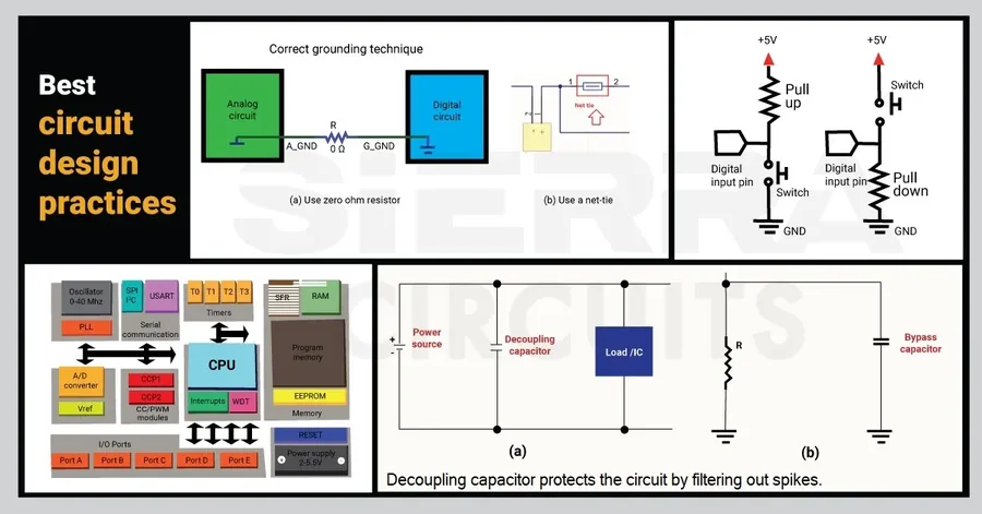
Power Supply Problems Inadequate power supply, be it insufficient voltage, insufficient current, or excessive noise, can cause IC logic gates to function incorrectly. Use a multimeter to check the voltage and current at the power pins of the IC. Ensure that the power supply is within the specified operating range as defined by the IC datasheet. Also verify the quality of your power supply; a noisy power supply can affect IC performance and even damage the IC. Add bypass capacitors near the IC power pins to filter out high-frequency noise.
IC Failures If a specific IC logic gate is consistently not functioning, the IC itself may be defective. Replace the IC with a known good one. If the circuit then functions correctly, the original IC was faulty. Often, ICs can be damaged by electrostatic discharge (ESD) or overheating during soldering or improper storage. Use proper ESD protection and be mindful of heat dissipation during soldering.
Input Signal Issues Ensure that the input signals to the logic gates are within the specified voltage levels for the IC. Use an oscilloscope to check the shape, amplitude, and timing of the input signals. Incorrect or out of spec input signals can cause the gate to behave erratically, or even damage the gate. Ensure proper signal integrity by using appropriate wire lengths and signal terminations.
Output Loading Excessive loading on the output of a logic gate can prevent it from operating correctly. Be certain that the load connected to the output is within the fan-out specification for the IC. Use a smaller load, if the logic gate output then works correctly, the load is excessive for the gate.
Environmental Factors Extremes of temperature and humidity can significantly affect the performance of IC logic gates. Ensure operation is within specified operational ranges in the IC datasheets. Ensure proper environmental control for testing and storage.
Basic Equipment for Troubleshooting: A multimeter, oscilloscope, and logic probe are useful for debugging these circuits.
By systematically checking these common issues and using the right diagnostic equipment, you can significantly reduce time spent troubleshooting IC logic gate circuits.
Future Trends in IC Logic Gates
The field of IC logic gates is undergoing continuous evolution, driven by the relentless demand for faster, more efficient, and smaller electronic devices. Current research focuses on novel materials, low-power designs, and miniaturization techniques to push the boundaries of logic gate technology and meet the ever-increasing demands of modern electronics and computing.
Emerging Materials Researchers are actively exploring alternative materials beyond silicon for fabricating logic gates. These include graphene, carbon nanotubes, and other two-dimensional materials, which offer the potential for higher electron mobility and improved performance compared to traditional silicon-based devices. The use of these materials could lead to faster switching speeds and reduced power consumption in future logic gate designs.
Low-Power Design Reducing power consumption is a crucial objective, particularly for portable and battery-powered devices. Ongoing efforts are focused on developing new architectures and fabrication techniques for logic gates that minimize power dissipation. This includes exploring techniques like voltage scaling, clock gating, and advanced transistor designs. Lower power consumption will not only extend battery life but also contribute to more sustainable electronic systems.
Miniaturization The trend towards miniaturization continues, driving the need to pack more transistors into smaller spaces. Nanofabrication techniques, such as extreme ultraviolet (EUV) lithography, are being used to create smaller and more complex logic gates. Further miniaturization allows for higher integration densities, leading to faster and more powerful devices while reducing size and cost.
Quantum Computing Logic Gates The development of quantum computing is introducing a completely new paradigm for logic gates. Quantum logic gates leverage quantum phenomena like superposition and entanglement to perform computations that are impossible with classical logic gates. This field is still in its nascent stages, but it holds enormous potential to revolutionize computation.
3D Integration Stacking logic gate layers vertically, rather than just horizontally, offers a path to higher integration densities and reduced interconnect lengths. This 3D integration approach promises better performance and lower latency, particularly in complex integrated circuits.
In conclusion, IC logic gates are the unsung heroes of the digital world. From basic switches to complex processors, they enable the functionality of countless electronic devices. This comprehensive exploration has shed light on their foundational role, covering their types, functions, applications and practical selection criteria. As technology evolves, we can anticipate further innovation in IC logic gate design, paving the way for even more powerful and efficient electronics in the future. Understanding IC logic gates not only enhances our understanding of technology but also illuminates the ingenious logic that underpins the digital world.